The above shown comparison of hydraulic resistance coefficients, obtained in various researches, show that in geometrically similar swirlers, in automodel zone the values of ![]() are close to each other. The most discrepancies of compared
are close to each other. The most discrepancies of compared ![]() are most likely caused by some structural differences of deferent routes. The obtained functions can be used in calculations of tangential swirlers.
are most likely caused by some structural differences of deferent routes. The obtained functions can be used in calculations of tangential swirlers.
In the past years research works on the number of high pressure hydrosystems (Rogun (Tadjikistan)-300m, Teri (India)-240m, Tupalang-172m, Telmam (Russia)-140m and others) have raised issues of development of principally new designs of water spillway structures, capable of working high flow velocity conditions (50-60m/sek). The solution of the given problem must meet the requirements for high reliability of structural elements of water spillway tact in all regimes of its exploitation and ecological safety, i.e. decrease of the negative effects of spilled flow on environment.
The most simple solutions are seen today on development of horizontal vertical shaft spillways with tangential flow swirler.
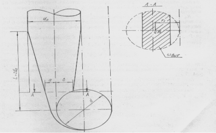
The main characteristic of discussed swirler is it geometrical parameter ![]() (pic.1).
(pic.1).
![]() (1)
(1)
where rt — the distance from the tunnel axes to weight center of inlet cross section with area of ![]() ; R — tunnel radius in shaft axes;
; R — tunnel radius in shaft axes; ![]() - tilt angle of the supply waterway to swirler.
- tilt angle of the supply waterway to swirler.
The value of parameter of flow swirling behind swirler П0 and other characteristics of flow mostly depend on design of swirling device. Obviously, the Очевидно, hydraulic resistances of swirler depend on the flow swirling intencity (П), developed by the swirler itself.

Fig.1. Tangential swirler scheme
П is the ratio of tangential component of shearing stress τu to full stress near wall τ, or, which is practically the same — the ratio of peripheral velocity Vu to full velocity near wall V:
![]()
There are significant pressure losses in the “swirling device — deferent spillway” system of the vertical spillway.
It is known that the coefficient of hydraulic resistance in tangential swirler is determined the following way [2, 3]:
 (2)
(2)
where ![]() — full specific flow energies in sections in front and behind the swirler averaged on cross section, ,
— full specific flow energies in sections in front and behind the swirler averaged on cross section, , ![]() — the values of dynamic head from full velocity in section behind swirler averaged on cross section.
— the values of dynamic head from full velocity in section behind swirler averaged on cross section.
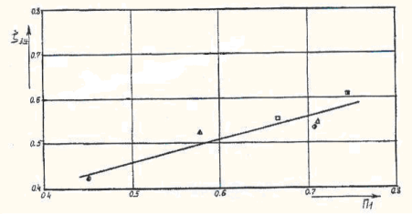
Our graphical results for values of resistance coefficients in swirler depending on the intensity of flow swirling on the outlet are shown in pic.2. Hydraulic resistance increases with the increase of the parameter of intensity of swirling, it changes from 0,42 to 0,6 according to the measurements of hydraulic regimes in the given work.
Generalized expression ![]() has a linear nature and is approximated with the following expression:
has a linear nature and is approximated with the following expression:
![]() (3)
(3)
with 0,42≤П≤0,75
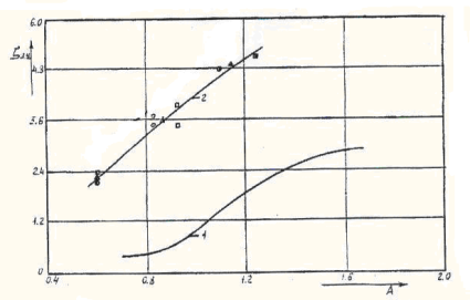
The graph of hydraulic resistance coefficient of tangential swirler with flat cut shaft vs. geometric parameter A, (the curve 1, received in work [4]), is shown on pic.3. In this work the values ![]() and
and ![]() from expression (2) were determined from average discharge velocity in round outlet section of swirling system, therefore
from expression (2) were determined from average discharge velocity in round outlet section of swirling system, therefore ![]() is substantially higher than the analogical values on pic.2.
is substantially higher than the analogical values on pic.2.
The dependence 2 is shown on pic 3., which is calculated the same way from the research data received by the author. Evidently, the both curves differ substantially. The reason for it is that the same value of the parameter A (even when the structure works in automodel zone) doesn’t provide the same structure of swirled flow behind the swirler. It is necessary that the swirling devices be geometrically similar.
This condition is an important aspect in modeling vertical water spillway structures.
As a result of analysis [5] conclusion was done, that during calculations one must use values of ![]() , determined on the outlet of swirler, because discharge coefficient, determined by these resistances (4), are similar to discharge coefficient, determined by discharge through weir gauge, head and wetted cross section area affecting on swirler on the outlet of swirling device (5):
, determined on the outlet of swirler, because discharge coefficient, determined by these resistances (4), are similar to discharge coefficient, determined by discharge through weir gauge, head and wetted cross section area affecting on swirler on the outlet of swirling device (5):

Fig. 2. Graphical results for values of resistance coefficients in swirler depending on the intensity of flow swirling on the outlet

Fig. 3. The graph of hydraulic resistance coefficient of tangential swirler with flat cut shaft vs. geometric parameter A
![]()
![]()
![]()
 (4)
(4)
 (5)
(5)
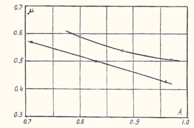
At the same time ![]() has changed from 0,35 to 0,55, which well conforms to the recommendations in reference book [1], where it is indicated that for tangential spiral chamber like swirlers one must approximately use
has changed from 0,35 to 0,55, which well conforms to the recommendations in reference book [1], where it is indicated that for tangential spiral chamber like swirlers one must approximately use ![]() until he gets more precise data.
until he gets more precise data.
The values ![]() , determined with average discharge velocity, are in range from 1,6 to 5,2, which well conforms to the dependence — 2 on pic.3.
, determined with average discharge velocity, are in range from 1,6 to 5,2, which well conforms to the dependence — 2 on pic.3.
It is seen from the expression (4), that the values μ and ![]() are interdependent. On pic.4 there are shown the functions of tangential swirler discharge coefficient values vs. flow swirling intensity on the outlet
are interdependent. On pic.4 there are shown the functions of tangential swirler discharge coefficient values vs. flow swirling intensity on the outlet ![]() .
.

Fig. 4. Discharge coefficient µ vs. geometrical parameter A graph:
—o- for swirlers with elliptical shaft cut
—x- for swirlers with flat shaft cut
The above function is approximated with the following expression:
![]() (6)
(6)
where 0,42≤П≤0,75
References:
- Hydraulic calculations of water spillway hydrotechnical structures: Reference book. Moscow, Energoatomizdat, 1988. 624 pages.
- Jivotovski B.A., Rozanova N.N., Sinichenko E.K. Short term recommendations on calculation and design of water spillways with rapid energy suppression of twisted flow. RUDN. 1992. 149.
- Sapfirov A.B. Assessment of hydraulic properties of vertical shaft water spillways with tangential flow swirler: Dissertation. ... candidate of technical sciences, MGMI, 1991.174 pages.
- Talant M.A., Jivotovski B.A., Novikova I.S., Rodionov V.B., Rodionova N.N. Properties of vertical tunnel spillways and hydraulic conditions of their work. // Hydrotechnical construction. 1995, 9 pages. 16-22.
- Khanov N.B. Vortical spillways with inclined shaft and tangential swirler. Dissertation, Doctor of technical sciences. MGMI, 1994.169 pages.

