Protections of converting installations, made on the traditional element base
Авторы: Барукин Александр Сергеевич, Кенес Махмутжан Алдиярулы
Рубрика: 7. Технические науки
Опубликовано в
LXI международная научная конференция «Исследования молодых ученых» (Казань, май 2023)
Дата публикации: 20.05.2023
Статья просмотрена: 2 раза
Библиографическое описание:
Барукин, А. С. Protections of converting installations, made on the traditional element base / А. С. Барукин, Махмутжан Алдиярулы Кенес. — Текст : непосредственный // Исследования молодых ученых : материалы LXI Междунар. науч. конф. (г. Казань, май 2023 г.). — Казань : Молодой ученый, 2023. — С. 9-13. — URL: https://moluch.ru/conf/stud/archive/492/18026/ (дата обращения: 27.04.2024).
It is stated that the use of differential protection in converter installations allows, in comparison with maximum current protection, to increase speed and sensitivity. It is mentioned that over the past 20 years a number of new protection devices for converter installations based on the traditional element base have been developed, two of which are considered in this paper. Their advantages and disadvantages are emphasized.
Keywords: converter installation, differential protection.
In the works of some authors (for example, [1, 2]), it is proposed to use differential protection (DP) to protect converters from internal damage. Compared to overcurrent protection, this allows for faster response and higher sensitivity. Detection of damage in the first moments of the occurrence of an emergency process is ensured due to the response of the DP to the difference between the input and output currents of the converter, as a result of which the signal to turn off the damage is given before the emergency currents reach critical values. In [2], one of the first DP converter installations was proposed. Over the past twenty years, a number of new protection devices for converter installations based on a traditional element base have been developed in the world, two of which are considered in this paper.
In the device [3], the prevention of the development of an accident is carried out due to the faster, in comparison with [2], disconnection of the short circuit current (SC). To do this, the blocking of the control pulses is carried out at the moment of completion of their next switching after the occurrence of SC. Thus, due to the fact that the serviceable thyristors of the damaged phase are open at this point in time, the damaged branch of the converter is shunted.
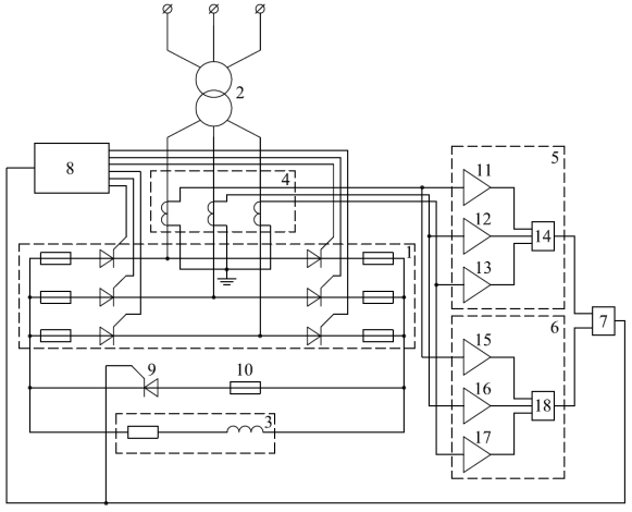
The device [3] for protection against developing SCs of thyristor converter 1 (Fig. 1, where 2 is a transformer, 3 is a load) consists of current transformers (CTs) of phases 4, circuit 5 for detecting SC current, circuit 6 for identifying the end of thyristor switching, and element AND 7, thyristor control unit 8, thyristor short circuit 9, fuse 10. Circuit 5 consists of maximum action comparators 11–13 and an OR element 14. Circuit 6 includes minimum action comparators 15–17 and an OR element 18.
The device works as follows. With CT 4 phases A, B, C converter 1, the signals are fed to the inputs of the comparators 11–13 and 15–17. The signals from the comparators 11–13 are fed to the inputs of the OR element 14, the logical "1" at the output of which appears in the presence of SC in the converter 1. The signals come to the inputs of the OR 18 element from the comparators 15–17, while the logical "1" at its output is a sign of the absence of current in one of the phases, which corresponds to the end of the switching of thyristors. The output signals of the OR elements 14 and 18 are fed to the input of the AND element 7. The presence of a signal at the output of the latter blocks the supply of pulses from the control unit 8 to the thyristors and opens the short circuit 9, which shunts the output of the converter 1. Connecting in series with the short circuit 9 fuse 10 allows to achieve a short circuit current limit. When the SC current is turned off, the logical "0" is set at the output of the OR element 14, and the signal is removed from the input of the AND element 7, as a result of which the supply of pulses from block 8 is resumed [3].
When used, for example, in power thyristor converters of excitation systems of synchronous generators, protection [3] will make it possible to avoid significant economic damage associated with an emergency shutdown of the generator due to the destruction of the converter. The disadvantage of the device [3] is the lack of redundancy for switching off the output current of the converter in case of failures of the main protection in emergency modes. With external short circuits, this can lead to failure of the internal and external circuits of the converter, which are under the influence of overcurrents.

Fig. 1
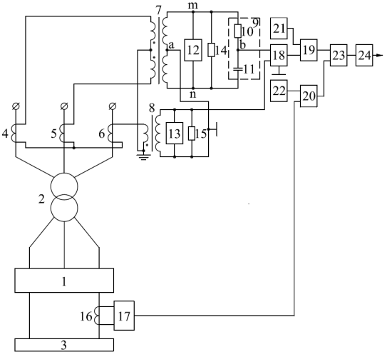
In [4], protection of converter installations from asymmetrical SCs is proposed, which contains (Fig. 2, where 1 is a rectifier; 2 is a transformer; 3 is a load; 4–6 are CTs of phases A, B, C from the high voltage side of transformer 2) intermediate CTs 7 and 8, phase-shift circuit 9 (consisting of resistor 10 and capacitor 11), filters 12 and 13 of higher harmonics, load resistors 14 and 15, CT 16 of the direct current path (DCP) circuit of rectifier 1, filter 17 of the first harmonic, adder 18, comparison circuits 19 and 20, blocks 21 and 22 for setting the settings, element AND 23, executive body 24.
The device works as follows. With asymmetric SCs, for example, with two-phase SCs at the terminals of the secondary winding of the transformer 2, the DCP circuit of the rectifier 1 also contains an alternating current component with a frequency of 50 Hz, as a result of which a signal appears at the output of the comparison circuit 20, which arrives at the second input of the AND element 23. When In this case, the primary currents of transformer 2, different in value and phase, can be decomposed into two symmetrical systems of currents — direct and reverse sequence. The presence of negative sequence currents leads to the appearance at the output of the adder 18 of a voltage sufficient to operate the comparison circuit 19, from the output of which the signal arrives at the first input of the element AND 23. The presence of signals at both inputs of the element AND 23 leads to the actuation of the executive body 24, from the output of which a signal is received to turn off the converter installation switch (not shown in Fig. 2) [4].

Fig. 2
For the reverse sequence of phase currents, the voltage


References:
- Krivenkov V. V., Novella V. N. Relay protection and automation of power supply systems. — M.: Energoizdat, 1981. — 328 p.
- Glukh E. M., Zelenov V. E. Protection of semiconductor converters. — M.: Energoizdat, 1982. — 152 p.
- Patent for invention No. 2197051 RF. A method and device for protecting a thyristor converter from developing short circuits // Andreev A. N., Goldstein M. E. Published 20.01.2003, Bull. No. 2. — 5 p.
- Patent for invention No. 2451378 RF. Device for protecting rectifier units of traction substations from asymmetric external and internal short circuits // Zimakov V. A. Published May 20, 2012, Bull. No. 14. — 9 p.


