


Research and improvement of laser interferometric system in the field of non-contact measurements of reference rings

Авторы: Москалев Андрей Андреевич, Rahman Ardi
Рубрика: Машиностроение
Опубликовано в Техника. Технологии. Инженерия №3 (9) июнь 2018 г.
Дата публикации: 21.05.2018
Статья просмотрена: 70 раз
Библиографическое описание:
Москалев, А. А. Research and improvement of laser interferometric system in the field of non-contact measurements of reference rings / А. А. Москалев, Ardi Rahman. — Текст : непосредственный // Техника. Технологии. Инженерия. — 2018. — № 3 (9). — С. 18-23. — URL: https://moluch.ru/th/8/archive/95/3390/ (дата обращения: 25.04.2024).
The general issues in the field of measurements of internal dimensions are represented. The laser interferometric system with non-contact probe placed in service at VNIIM for high-accurate measurements of reference rings is described. The results of theoretical research of the components of uncertainty of measurements, as well as the possible ways for their minimization, are given.
Keywords: metrology, reference rings, setting rings, unit of length, standards, laser interferometer.
Introduction
Measurement of internal dimensions and especially internal diameter of cylinder gauges is the topical issue of modern metrology. Cylinder gauges (setting rings and reference rings) are widely used for calibration and verification of measuring instruments such as bore gauges or high-precision horizontal comparators.
The level of accuracy in measurements of any kind of gauges and standards gets higher in response to increasing demands of modern industry and science. As it concerns to reference rings, it’s necessary to say that the internal diameter gauges were included as the first echelon standards into the latest edition of the Russian national traceability chain published in 2011 [1]. The highest accuracy level for this type of standards was the second in the previous version of the document [2]. The extract from the current traceability chain is given on the figure 1. According to the new document the unit of length — meter has to be transferred from the reference standard to the secondary standard, then to internal diameter gauges (rings) of the first echelon and then down the chain. Direct measurements should be performed in all cases. The secondary standard used in this part of the chain (shaded box on the fig. 1) is the laser interferometric system developed by VNIIM and designed for internal measurements. The set will be described in details in the following part of the article. Note that this system was added into the chain as well as the rings of the first echelon due to demands from industry mentioned above.
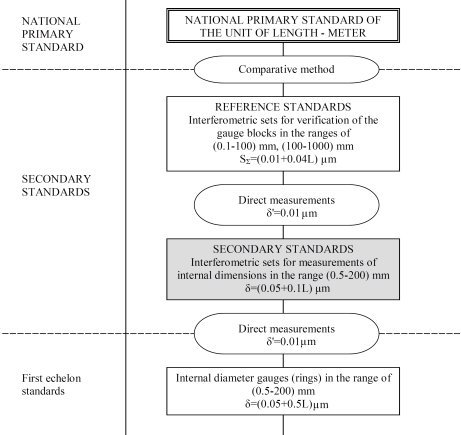
Figure 1. The extract from the national traceability chain: SΣ — standard deviation of combined inaccuracy of measurement; δ — absolute error of measurement with the level of confidence 0.99; δ’ — absolute error of the measuring method; L — length in meters
Laser interferometric system for internal measurements
The system used in VNIIM for measurements of internal dimensions consists of a horizontal comparator and a laser interferometer. The main feature of the system is the optical probe (also called ‘perflectometer’ in some sources) for non-contact pointing at the gauge surface. Using the tactile probe for the same purpose, obviously, causes contact deformation, which may affect the results, and the measuring range limitation depending on the probe size.
The general concept of the optical probe is given on the figure 2.
The functional idea is the following [3]. The light from the source S propagates through the aperture and then the objective lens O1 forms the primary image S1 as the light mark. The image S1’ is the reflection of the S1 from the gauge surface. The lens O2 focuses both images on the plane F. There the image S2 has the same shape as the aperture S, and the image S2’ has the shape of the reflected gauge surface (a segment of circle in case of internal diameter measurement). When the gauge surface takes position of S1, the image S2 will be replaced by the image S2’.
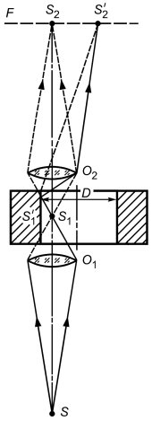
Figure 2. Optical probe: S — light source aperture; S1 — primary image of the light mark; S2 — secondary image of the light mark; O1, O2 — objective lenses; F — image plane
This means that the one side of the gauge surface is acquired. To find this position more precise the photo detector mounted in the image plane F is used to transform the reflected images into electrical signal. When both light marks S2 and S2’ are aligned in one point the detector gives the zero readout.
Then the gauge should be moved to perform the same procedure on the opposite side of the gauge surface. The distance between two points (D) is measured by laser interferometer.
The general setup of the measuring system in combination with the optical probe is given on the figure 3. The ring (1) is placed and fixed on the movable table on the axis of the optical probe. The light mark from the source (2) reflects from the gauge surface and the image produced is captured by the detector (3). The measuring system consists of a stabilized He-Ne laser (5) with the wavelength λ=633 nm which movable reflector (4) is attached to the table. So the horizontal displacement of the table gives the distance between two points on the opposite sides of the gauge surface, that is an equivalent of the internal diameter.
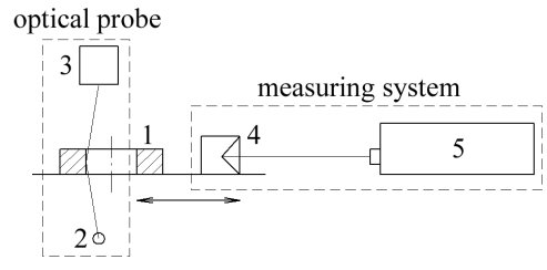
Figure 3. Measuring setup: 1 — measuring item; 2 — light source of the optical probe; 3 — photo detector of the optical probe; 4 — movable reflector of the measuring system; 5 — laser
The setup has some more parts not mentioned on the figure 3, such as electronic counters and digital devices for interference pattern processing, temperature stabilization system etc.
Research of the uncertainty of measurements
The mathematical model of internal diameter measurements can be represented as
|
|
(1) |
where d — diameter of the gauge at the temperature of 20 ºC in mm;
N — interferometer readout;
λ — wavelength of the laser source, mm;
n — air refractive index;
Δtm = (20 — tm) — deviation of the gauge temperature tm from normal, ºC;
α — thermal expansion coefficient of the gauge material, K-1;
D — nominal diameter of the ring, mm;
ΔP — correction depending on the uncertainty of the optical probe performance, mm;
Δi — correction depending on the instrumental error of interferometer system, mm.
This model gives the following result of the expanded uncertainty of measurements with the coverage factor k=2 [4]:
|
|
(2) |
This was represented by VNIIM as the results of international comparisons of internal diameter gauges in the COOMET project 181/RU/99. The formula was corrected after further research and then published in the BIPM CMC database as given (updated on December 28th 2012):
|
|
(3) |
At the other hand, increasing demands from industry require higher precision of measurements at every level. In 2013 the first echelon standard of the unit of length based on the high-accurate horizontal instrument was placed in service at VNIIM. The general application domain of this instrument is measurements of gauge blocks, reference rings and plugs, thread gauges. The higher precision achieved with the expanded uncertainty of measurements of gauge blocks is less than 20 nm [5]. The unit of length can be transferred to this standard both from the laser measuring system of the National primary standard and from the Secondary standard by measuring of the reference ring. That’s why we need the Secondary standard to be more accurate.
There are several ways to minimize some of the uncertainty components given above. The first one that seems to be the most obvious is to upgrade the measuring system with the new commercially available laser with resolution less than 10 nm. This will reduce the readout error component, which is highly depends on this parameter. The second one to be minimized is instrumental error of the system. In fact it means the measurement error caused by the angle between laser interferometer beam and the axis of the table displacement. The angle value taken into calculation in ref. 4 is not less than 3’ and it’s limited by the interferometer design aspects. However, the modern laser set with more flexible adjustment system in combination with the research of instrumental error using autocollimator for table displacement alignment can reduce the angle value mentioned to Ω=1.5’.
Using these values, as well as the latest optical probe research results for the uncertainty of the light mark positioning, we represent all the components in the table 1.
Table 1
Uncertainty budget
|
Input quantity xi |
Standard deviationu(xi) |
Sensitivity coefficient ci=δd/δxi |
Standard uncertainty ui(d), μm |
|
N |
10×10–7 m |
√2 |
0.014 |
|
ΔP |
1.5×10⁻⁸ m |
√2 |
0.021 |
|
λ |
3×10⁻⁸ m |
D |
0.03×10⁻³×D |
|
n |
1.8×10⁻⁷ m |
D |
0.18×10⁻³×D |
|
Δi (Ω=1.5’) |
0.2×10⁻⁶ m |
D |
0.2×10⁻³×D |
|
Δtm (α=11×10–6×K-1) |
0.01 K |
α×D |
0.12×10⁻³×D |
|
α |
0.5×10⁻⁶ К-1 |
∆ tm ×D |
0.005×10⁻³×D |
Calculation of the expanded uncertainty with the coverage factor k=2 according to the GUM [6] gives the following result:
|
|
(4) |
The accuracy performance of the laser interferometric set by VNIIM expected according the formula 4 is shown in figure 4 as well as the accuracy characteristics specified in the traceability chain.
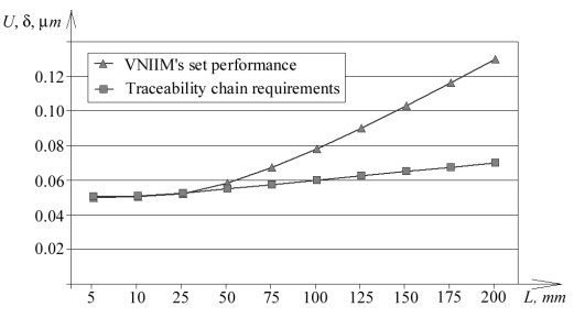
Figure 4. Expected performance of the measuring set by VNIIM compared to the traceability chain accuracy requirements
The uncertainty is given as function of measuring length (or diameter in case of measurement of reference rings). The range from 5 to 25 is scaled to fit the axis steps in the graph. As we see, both lines are nearly identical in the range up to 50 mm. The uncertainty of measurements is obviously highly affected by the components depending on the measuring diameter, so reduction of these components should be the topic of further research.
Conclusion
Here we declared the general setup of the laser interferometric system made by VNIIM for internal measurements of reference rings as well as some methods applied for minimization of the uncertainty components.
Further steps will be taken to optimize the system to make its performance better. At first we will use the real-time thermal compensation system to have the clear view of temperature gradients in the volume of the measuring set. The system of 2 up to 6 thermal sensors with the special software by “Trimos S. A.” is going to be used. The similar one is already launched successfully at the first echelon standard of the unit of length mentioned above [7]. Then we will replace the photo detector of the optical probe with the CCD camera and the software for digital image processing. At the same time the measuring table will be equipped with servo drives with the active feedback from the optical probe to make the system acquire diameter points automatically or by remote control. This will make the optical probe performance more accurate and also it will reduce human factor effects as well as the temperature deviations caused by human presence in the laboratory. The steps described will lead to the automation of the entire measurement procedure and the highest accuracy.
References:
1. GOST R 8.763–2011.State System for Ensuring Uniform Measurement. State verification schedule for measuring instruments in the range of length from 1·10–9 to 50 m and wavelength in the range of 0.2 to 50 μm. Date of validity 13.12.2011. M.: Standardinform. — 2013. — 8 p.
2. MI 2060–90. State System for Ensuring Uniform Measurement. State verification schedule for measuring instruments in the range of length from 1·10–9 to 50 m and wavelength in the range of 0.2 to 50 μm. Date of validity 01.01.1991. M.: Standards Publishing. — 1991. — 9 p.
3. F. T. Farago, M. A. Curtis. Handbook of Dimensional Measurement. NY. Industrial Press Inc. — 1994. — 580 p.
4. L.Yu. Abramova, V. M. Brzhezinskii, E. B. Bryukhovetskaya, V. S. Solov’ev, L. F. Khavinson. The COOMET Comparisons of the Standard Measures of Internal Diameters // Measurement Techniques. — Vol. 49. — № 1. — 2006. — P. 87–92.
5. Yu.G. Zakharenko, N. A. Kononova, A. A. Moskalev. Measurements of the Geometric Parameters of Thread Gauges // Measurement Techniques. — Vol. 59, Issue 2. — 2016. — P. 137–141.
6. JCGM 100:2008. Evaluation of measurement data — Guide to the expression of uncertainty in measurement. — 2008. — 134 p.
7. A. Mosckalev. High-accurate measurements of thread gages using the Labconcept NANO horizontal instrument // 24th National scientific symposium with international participation «Metrology and metrology assurance 2014». Proc. — Sozopol. — 2014. — Р. 480–485.
Ключевые слова
metrology, reference rings, setting rings, unit of length, standards, laser interferometerПохожие статьи
Uncertainty as inevitability of international standardization process of...
2. JCGM 100:2008 Evaluation of measurement data — Guide to the expression of uncertainty in measurement.
St.-Petersburg: VNIIM and.
Основные термины (генерируются автоматически): GUM, ISO, VNIIM, BIPM, SKO, ISOIEC, IFCC, IEC, GSI, AQD.
Похожие статьи
Uncertainty as inevitability of international standardization process of...
2. JCGM 100:2008 Evaluation of measurement data — Guide to the expression of uncertainty in measurement.
St.-Petersburg: VNIIM and.
Основные термины (генерируются автоматически): GUM, ISO, VNIIM, BIPM, SKO, ISOIEC, IFCC, IEC, GSI, AQD.
