


The heat pump
Библиографическое описание:
Зипа, А. В. The heat pump / А. В. Зипа. — Текст : непосредственный // Технические науки: проблемы и перспективы : материалы I Междунар. науч. конф. (г. Санкт-Петербург, март 2011 г.). — Санкт-Петербург : Реноме, 2011. — С. 55-58. — URL: https://moluch.ru/conf/tech/archive/2/157/ (дата обращения: 24.04.2024).
The heat pump – the device for carrying over the thermal energy from thermal energy source (with low temperature) to the consumer (heat-carrier) with more heat. Theoretically heat pump represents a return refrigerator [1, p.287].
The author offers the developed scheme of the heat pump – (Drawing 1):
1 – the compressor, 2 – the condenser, 3 – the expansion valve, 4 – the evaporator, 5 – the electromagnetic switch of operating modes of a refrigerator. The heat exchanger – 6 and a capillary tube – 7 are included into the scheme to increase an overall performance of the heat pump, the return valve – (8).
In the mode "cooling" to set temperature tr of a room, the traditional refrigerating cycle is carried out in a refrigeration unit (Drawing 2). The compressor – 1 compresses vapor of the refrigerant from pressure Pb (a point 1) to Рc (a point 2). Then vapor of the refrigerant move in the condenser – 2 where there are heat removing from the refrigerant, its cooling and condensation (process 2-7). Leaving the condenser – 2, the liquid refrigerant passes through expansion valve – 3 (process 6 - 5), where its pressure falls from Рc (a point 6) to Рb (a point 5). After that the refrigerant advances in the evaporator – 4, boils at temperature t0 and takes away heat from the room (process 5-1 ´). Process 1 '-1 is a heating of vapor of the refrigerant in the suction line. Further the cycle repeats.
In the mode "heating" to set temperature tr of a room, cycle in the refrigeration unit is carried in the opposite direction. The compressor – 1 pumps vapor of the refrigerant through the electromagnetic switch – 5, being in a "winter" operate mode, on line "A" in the evaporator – 4 (which executes of the condenser function), where heat Qe + Δ Qe transfers (process 8-9, Drawing 1) from the refrigerant to air of a heated room. After a heat supply in a room, the liquid refrigerant advances in pipeline "B", not arriving in pipeline C, because of mounted return valve. Passing through the heat exchanger – 6, the liquid refrigerant overcools on value ∆qhe (process 3-3 ´, Drawing 1,2), lowering pressure from Рc (a point 3) to pressure Рb (a point 4), through a capillary tube – 7. Then the liquid refrigerant advances in the condenser – 2 (which executes the function of evaporator), where the boiling of the refrigerant and the heat removing from air take place. The further movement of vapor of the refrigerant through the electromagnetic switch – 5, is carry out in the compressor - 1, and the cycle repeats. In this case, we receive the heat pump.

Power efficiency of the heat pump is characterized by its heat factor µ. It shows the ratio of produced heat (Q) to the power spent (N) for realization of a cycle:
μ =Q/N
Therefore, analyzing a work performance of the refrigeration unit, permanent heat factor inspection is necessary. According to the basic laws of thermodynamics, if the heat factor is more than one (μ > 1) the heat pump will transfer energy in the form of heat in a room μ times more, than it is spent power N [2, p. 510, 3].
Calculation of an operating mode of the developed heat pump was executed for the entry conditions:
Temperature in warmed room – tr = from 18 to 35 °С;
Ambient temperature – ta = from 0 to - 20 °С;
Capacity of the heat pump - Qо = 20 kw;
The refrigerant - R134a.
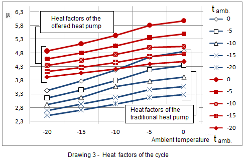
Conclusion: As a result of researches the increase in heat factor has been received on 11 % - 40 % (Drawing 3).
The offered scheme of the developed heat pump promotes savings of electric energy on 20 % - 44 %.
- References:
Bykov A.V. i dr. Holodil'nye mashiny i teplovye nasosy (Povyshenie effektivnosti) [Refrigerators and thermal pumps (efficiency increase)]/ A.V. Bykov, I.M. Kalnin', A.S. Kruze.- M.: Agropromizdat, 1988. [in Russian]
Holodil'nye mashiny: Ucheb. dlja vtuzov po special'nosti “Holodil'nye mashiny i ustanovki” [Refrigerators: Studies. For technical colleges on a speciality “Refrigerators and installations”]/ N.N. Koshkin, I.A. Sakun, E.M. Bambushek, i dr.; Pod obshch. red. I.A.Sakuna. – L.: Mashinosroenie, Leningr. otd – nie. - 1985. [in Russian]
Martynovskij V.S. Analiz dejstvitel'nyh termodinamicheskih ciklov [Analysis of the valid thermodynamic cycles]. M., Energija, 1972. [in Russian]


