


The paper studies and analyzes the performance of the system of lambda regulation for automotive internal combustion engines, which is an important component of the engine control system. Lambda regulation system is represented as a model developed in MATLAB. The results of modeling have enabled the author to improve the model of lambda control system which significantly improves the performance and accuracy of the lambda regulation system and results in better environmental and dynamic performance of vehicles.
Modern requirements to motor cars cannot be met without the application of modern control systems. Prominent among the vehicle control systems is the internal combustion engine control system with forced ignition. The engine control system provides optimal control actions, namely, the specified fuel-air mixture and ignition timing in order to insure high operating performance of the automobile, such as environmental performance, fuel efficiency, and dynamic performance.
An important component of the engine control system is a subsystem for the regulation of the fuel-air mixture composition according to the composition of the exhaust gases. In modern cars the subsystem is implemented as an algorithm of microprocessor engine control unit and is called lambda regulation subsystem, lambda regulation algorithm or lambda regulator.
The name lambda regulation comes from the name for the excess air ratio λ accepted in English literature. In Russian literature the excess air ratio is denoted as α. Thus, a more exact Russian name is alpha regulation algorithm. Nevertheless, the term lambda regulation is already generally accepted in Russian literature.
Let us briefly examine the device and principles of operation of lambda regulation system. The system block diagram is shown in fig.1.
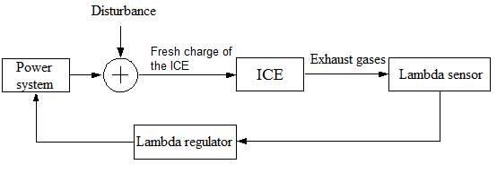
Fig. 1. Block diagram of lambda regulation system
Lambda sensor is an electrochemical sensor [2, p.43], which is installed in the exhaust system and is constantly washed by the engine exhaust gases. The output voltage of the lambda sensor changes according to the ratio of oxygen and oxidizable products (CO, CH) in the exhaust gases. Accordingly, low voltage results from the increased relative oxygen content in the exhaust gases and high voltage — from the increased relative content of products capable of oxidation (CO, CH). There is obviously a relationship between the ratio of oxygen and products capable of oxidation in the exhaust gases and the composition of the engine fuel-air mixture [3, p.68]. Figure 2 shows the dependence of lambda sensor voltage on the composition of the fuel-air mixture.
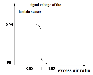
Fig. 2. Characteristics of the lambda sensor
Voltage dependence of lambda probe in the vicinity of stoichiometric mixtures is steep. This is due to the change in the direction of electrochemical reactions on the lambda sensor surface. Lambda sensor can be considered as a threshold element having two stable states:
fuel-air mixture is rich, the excess air ratio is less than unity, the voltage of the lambda sensor is high;
fuel-air mixture is lean, the excess air ratio is more than unity, the voltage of the lambda sensor is low.
Lambda sensor has a certain inertia both as a delay determined y the final velocity of the exhaust gases and as an aperiodic (delay) inertial element [1, p. 121].
Lambda sensor signal is processed by the lambda regulator, which is an integral or proportional-integral regulator. At the regulator inlet there is a threshold element with hysteresis to enhance noise immunity. If the lambda sensor signal value is high, the fuel supply decreases because of negative feedback, and vice versa.
At the regulator inlet there is a threshold element with hysteresis to improve noise immunity. If the lambda sensor signal value is high, the fuel supply decreases according to the principle of negative feedback, and vice versa.
Lambda regulator controls the fuel system of the engine. The output signal of the regulator is the coefficient of the excess fuel in the fuel-air mixture supplied to the engine. Coefficient of the excess fuel is reciprocal of the coefficient of the excess air.
The engine fuel-air mixture is fed with the coefficient of excess fuel predetermined by lambda regulator. The controller action is superimposed by the disturbance caused by the instability of the fuel system operation. For example, when fuel is injected into the intake manifold by electromagnetic nozzles there are changes of the regime of the engine, the pressure on the nozzles, the air and fuel density, etc.
The engine, as an object of control, is characterized by a certain inertia both as a delay determined by the finite velocity of the fuel-air mixture and exhaust gases and as an aperiodic (delay) inertial element with a time constant determined by the rate of precipitation and evaporation of fuel from the walls of the intake manifold [1, p.137]. It is a so-called effect of movement of the fuel film on the walls of the intake manifold.
To investigate the system of lambda control a model was developed in MATLAB system. The block diagram of the model is shown in figure 3.
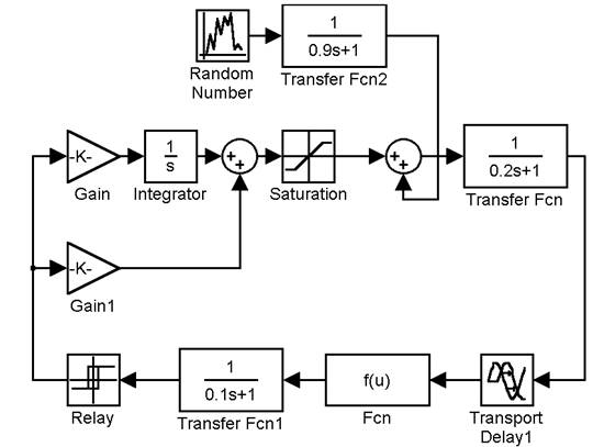
Fig. 3. Block diagram of the model of lambda control system
Let's describe the use of the model elements. Lambda sensor model consists of the following blocks: Transport Delay 1, Fcn and Transfer Fcn 1, which respectively simulate response delay, nonlinear and inertial properties of the lambda sensor.
Lambda sensor signal is processed by the lambda regulator on the units: Relay, Gain, Gain 1, Integrator Sum, Saturation. Relay unit is a threshold with hysteresis. Gain and Gain 1 determine the transfer coefficient of integral and proportional element. At the regulator output there is a restriction unit (Saturation). When building the model of the regulator the parametres for the engine control system of the VAZ January 5.1 family of cars were used.
Random disturbance modeled by Random Number and Transfer Fcn2 units is imposed on the output signal of the regulator. Standard deviation of a random variable is 0.03. Transfer Fcn2 unit is used to limit the range of a random variable according to the actual fluctuations in the fuel supply.
Transfer Fcn1 and Transport Delay1 units simulate the engine. Time constant of the delay element of Transfer Fcn1 is determined by the movement of the fuel film on the walls of the intake manifold. Transport Delay1 unit simulates transport delay depending on the finite velocity of the fuel-air mixture and exhaust gases through the engine.
Figures 4–7 show the simulation results of lambda control system.
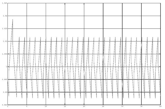
Fig. 4. The output of the lambda regulator in the absence of disturbances in the system
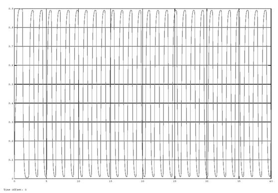
Fig. 5. The output of the lambda sensor in the absence of disturbances in the system
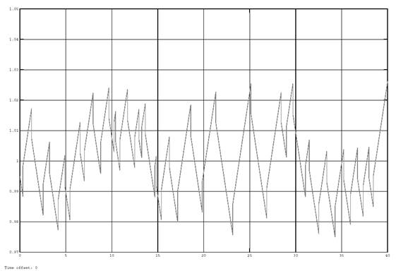
Fig. 6. The output signal of the lambda regulator with the disturbing effects in the system with a standard deviation of 0.03
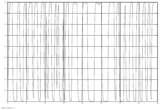
Fig. 7. The output signal of the lambda sensor with the disturbing effects in the system with a standard deviation of 0.03
The analysis of the graphs in figures 4–7 shows that the process of lambda control is periodic. The period of oscillation is about 1.25 seconds. Signal swing at the regulator output determines the accuracy of the regulation and is about 2.5 %. When the system is disturbed the oscillation period is a random variable ranging from 0.5 to 5 seconds, and the signal swing at the regulator output is about 5 %.
The performance and accuracy of the system of lambda regulation can be significantly improved if instead of the threshold element with hysteresis, the transfer function of which is shown in figure 8a, we will use the threshold element with inverse hysteresis, the transfer function of which is shown in figure 8b. In the literature, a kind of nonlinearity with inverse hysteresis is referred to as advanced nonlinearity [4, p.308, 314].
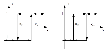
Fig. 8. Characteristics of the threshold element with hysteresis (a) and with inverse hysteresis (b). The arrows indicate the direction of change in the input variable
The timing diagrams illustrating the operation of the threshold element with direct and inverse hysteresis are shown in figure 9.
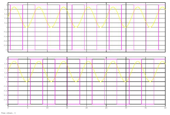
Fig.9. Timing diagrams of the operation of the threshold element with direct (top) and inverse (bottom) hysteresis
Lambda control system model, which uses a threshold element with inverse hysteresis is shown in figure 10.
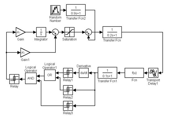
Fig. 10. Lambda control system model using a threshold element with inverse hysteresis
The model of the improved lambda regulation system with improved lambda regulator, engine and lambda sensor is completely similar to the model shown in figure 3. The differences lie in the threshold element in the units Derivative, Relay 1–3, Logical Operator and Logical Operator1. The block diagram of the threshold element with inverse hysteresis is of little interest as it is implemented as an algorithm.
Figures 11–14 show the results of modeling the system of lambda regulation. The analysis of the graphs in figures 11–14 show that the oscillation period is less than one second, the signal swing at the regulator output is about 2 %. When the system is disturbed the oscillation period is a random variable ranging from 0.1 to 1.8 seconds and the signal swing at the regulator output is about 4 %.
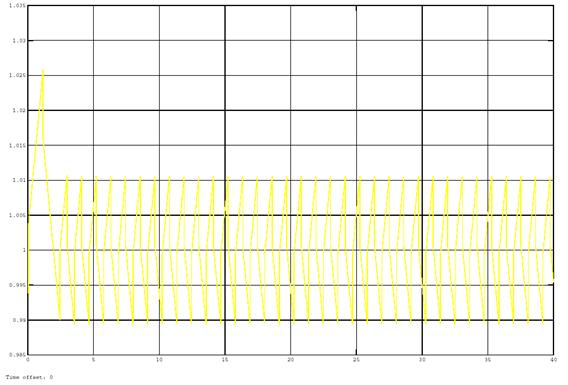
Fig. 11. The output signal of the lambda regulator of the improved system of regulation unaffected by disturbances
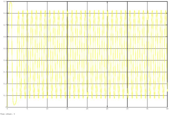
Fig. 12. The output signal of the lambda sensor of the improved system of regulation unaffected by disturbances
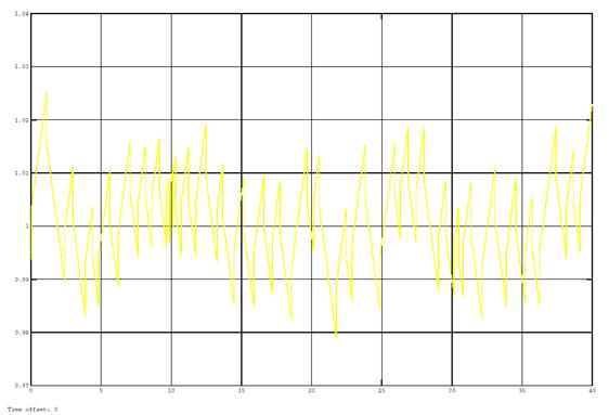
Fig. 13. The output signal of the lambda regulator of the improved system of regulation under disturbances with a standard deviation of 0.03
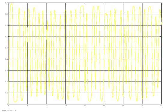
Fig. 14. The output signal of the lambda sensor of the improved system of regulation under disturbances with a standard deviation of 0.03
The application of the threshold element with inverse hysteresis in the system of lambda regulation improves the accuracy and performance of the system. The improvement of the accuracy and performance of the lambda regulation system that is maintaining more accurate stoichiometric composition of the mixture will result in better environmental and dynamic performance of vehicles.
Currently, a model for testing the improved system on the vehicle is being developed.
References:
1. Гирявец А. К. Теория управления автомобильным бензиновым двигателем. М: Сторойиздат, 1997г., 161 л.
2. Фатееев В. Н., Химические датчики на основе твердых электролитов. М: МХТИ, 1998г., 78 л.
3. Брозе Д. Д., Сгорание в поршневых двигателях. М., «Машиностроение», 1969г., 248л.
4. Пальтов И. П. Качество процессов и синтез корректирующих устройств в нелинейных автоматических системах,. Главная редакция физико математической литературы изд-ва. «Наука», 1975., 368 л.
