The paper examines the possibility of improving the efficiency of a hot water boiler plant by replacing the coolant (water) purchased from Zhairemsky GOK with coolant from the reverse piping of the GOK heating system.
Keywords : hot water boiler plant, coolant, cost of coolant.
The POFi hot water boiler plant is part of the Zhairem township's mining and processing plant and serves to supply the town with heat energy.
In order to meet the heating and hot water needs of the population, water in an open heating system is not only used as the heating medium of the heating system, but is also partially disassembled from the hot water supply network [1].
Water for heating main is purchased from Zhairemsky GOK in the amount of 130 t/h. At the cost of one tonne of water of 17 roubles. 12 kopecks per hour the cost of water purchase is 2225.6 rbl./h. Water is purchased during the heating season, 210 days, at a total cost of 2225.6 × 24 × 210 = 1,1217024 rubles. [2].
The modernisation of the heating network make-up in a hot water boiler plant is intended to reduce the costs of water purchase, which will also reduce the costs of electricity and water treatment [2–5].
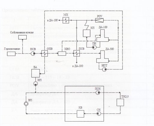
The existing thermal scheme is shown in Figure 1.
Raw water from the drinking water system is pumped by raw water pumps to the WWTP, where it is heated by make-up water to a temperature of 40°C and then passed on to the chemical water treatment plant (CWTP). In the chemical water treatment plant the raw water is freed from calcium, magnesium, iron ions and suspended solids to a certain value.
The treated water is divided into two streams:
– heating network make-up water (140 t/hour);
– the feed water of steam boilers (15 t/hour).
Make-up water (after the first treatment stage) goes to the boiler plant (PSV-315), where it is heated by steam from the superheated steam pipeline (steam temperature 250ºC) and then fed to the deaerator head (DA-300).
The deaerated water is collected in the deaerator accumulation tank, from where it is pumped to the network water coolers as a heating medium, where it is cooled down to 70ºC, and is directed to the heating network make-up pipe of heat mains 18 and 19 and to the accumulation tanks (BA). From the storage tanks, deaerated water is fed by transfer pumps (PP) to make-up water in the return pipeline of heat mains 18 and 19 during 'peak' times of hot water supply.
From the return routing, water is sent to the pump room of the boiler house to the pumps (PSN) and fed to return routing 23 at GOK-3.
At WWTP 3, the water is heated to a specified temperature and returned via a straight line 23 to the suction of the network pumps (SN) of the boiler house water pumping station [1, 3, 6].
The water is then pumped by pumps (CH) to the hot water boilers, where it is heated to the target temperature. From the hot water boiler it is sent to direct heating lines 18, 19 [6].

Fig. 1. Initial heat map
The second flow of chemically treated water after the first treatment stage is fed to the second stage — the Na-cationic-exchangers, where the water is treated to a predetermined level of hardness salts.
The water then enters the chemically treated water preheater, where it is heated to a temperature of 90ºC and fed to the deaerator heads (DA-100). To the deaerator head (DA-100) simultaneously with chemically treated water the condensate from steam cooler PSV-315 arrives and condensate from condensate tanks 1, 2 is supplied by condensate pumps (NKB). The water is treated to the preset indicators from hardness salts.
Thus, the feed water of steam boilers has four components:
1) CWA (chemically treated water);
2) condensate from the PSV;
3) condensate from the condensate tanks;
4) condensate from the MX.
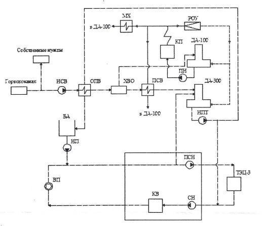
Figure 2 shows the modernised heat map for the Pofi boiler plant. The main elements of the heat scheme are shown in the table below.
Water from the Zhairemsky GOK's water pipeline in the amount of 20 t/h passes raw water pumps (WWP), preheaters (RWP) and enters the chemical water treatment plant (CTP).
Then the water in the chemically treated water preheater is heated to 90ºС and directed to the deaerator DA-100, where simultaneously the condensate from the fuel oil farm (MH) and from the condensate tanks is supplied by condensate pumps (NCP). In the deaerator (DA-100) corrosive gases are removed from water and it is heated up to 104 ºС by steam generator steam (KP-steam generator GM-50), passing through the ROU. The deaerated water is collected in the accumulating tank of deaerator DA-100, from where by feeding pumps.
The PEN is fed to the steam generator (PC), which acts as the peak boiler for the cogeneration system.

Fig. 2. Modernised thermal scheme of the POFi boiler house
Table 1
List of main elements of the system
|
Designation |
Name |
Qty |
|
KP |
Steam generator GM-50 |
2 |
|
EF |
Water heating boiler KVGM-100 |
4 |
|
NSV |
Raw water pump 200D-90 |
2 |
|
NSV |
Raw water pump KM-100–80–160-C |
2 |
|
PN |
CNSG-60–264 feed pump |
3 |
|
PNT |
Heating system make-up pump SE-500–70 |
3 |
|
PNT |
Heat mains make-up pump KS-125–55 |
2 |
|
NP |
Transfer pump SE-500–70 |
2 |
|
CH |
Network pump SE-1250–140 | |
|
PSN |
Transfer network pump SE-2500–60–11 |
4 |
|
OPV |
TP-800 |
4 |
|
PSV |
PSV-315–14–23 |
2 |
|
ROU |
Reduction and cooling unit |
2 |
|
YES |
Deaerator DA-100 |
2 |
|
YES |
DA-300 deaerator |
2 |
|
BA |
RVS-5000 storage tanks |
2 |
|
MH |
Fuel oil facility | |
|
HBO |
Water treatment | |
|
EP |
External consumer |
To make up for the heating main, water is taken not from the Zhairemsky GOK water pipeline, but from the return pipeline of the heating main at 65ºC. The water is supplied to a deaerator (DA-300), where it is deaerated and heated to a temperature of 104ºC. The produced water is collected in the deaerator accumulation tank, from where it is sent to the suction line of the CH network pumps by the heating system booster pumps [1, 3, 6]. [1, 3, 6]. The storage tanks are filled with water during times of low load on the district heating network, mainly at night. Source water for the system at KGOK-3 is taken from a natural source and undergoes the necessary treatment, purification and preparation in the chemical water treatment shop.
The new scheme has a number of advantages over the original one. Firstly, the water received from consumers is recycled.
Secondly, there is no need for water treatment as the water has been treated and heated before primary use, reducing the cost of filtering, heating and deaerating the water.
Thirdly, as the water comes in after preheating, it can be used to heat the heating medium in the heating pipeline.
The implementation of the modernised heat scheme of the hot water boiler house allows the reuse of return flow water from the mine's district heating system to reduce the volume of water purchased from the Zhairemsky mine from 130 to 20 t/h [4].
References:
- Rotov, P. V. Improvement of energy efficiency of GOK and urban heat supply systems / V. I. Rotov, Sharapov // Electric Stations. 2018. — № 9.
- Instruction on the introduction of a water-chemical regime of the Dzemgi water- heating plant, KGOK-3.
- Rotov, P. V. Peculiarities of Heat Supply System Load Control during Transition Period / V. I. Rotov, V. I. Sharapov // Power Supply and Water Treatment. — 2015. - № 2.
- Samsonov V. S. Economics of enterprises of power complex: textbook for universities / V. S. Samsonov, M. A. Vyatkin. — 2nd ed. — Moscow: Higher School, 2017. — 416 с.
- Rotov, P. V. Comparison of Energy Efficiency Indicators of the Heat and Power Plant for Qualitative and Quantitative Heat Load Regulation / P. V. Rotov // Electric Stations. — 2015. — № 10. — С. 19–23.

