


Abstract. Understanding the full aspects of hybrid grid operation that includes electrical and mechanical aspects are very critical to completely study this perspective operation. Therefore, this paper presents a hybrid generation system that is supplied with a Stirling engine (SE) and a wind turbine. The entire system is linked to a grid over a common dc bus. After combining wind turbine with the Stirling, an efficient hybrid system is created due to the fact the Stirling considered to have efficiency more than photo voltaic array. In order to structure the wind turbine mechanical parts, Stirling engine, electrical parts, Fatigue, Aerodynamics, Structures, and Turbulence (FAST) and Simulink/MATLAB are used. Moreover, voltage source converter is used to develop field-oriented control method. Nevertheless, determining the generators reference spear speed in the system hybrid is achieved through implementing the power signal feedback method. More efficiently, the Wind Turbine and Stirling engine utilize permanent magnet synchronous generator. The simulation outcomes present a novel hybrid generation system with Wind Turbine and Stirling can operate such as other hybrid systems with a very suitable performance.
Keywords: smart grid, heat engine, modeling, simulation, wind turbine, Stirling engine (SE), hybrid system (HS).
I. Introduction
The requirements to reduce pollutant gas emissions and the liberalization of the electricity market have led to a large-scale development of distributed renewable energy generators in electrical grids. Todays, photovoltaic or wind power generators (renewable energy generators) are widely spread technology. According to the recent Annual Energy Outlook (AEO), in next following decades, residential electricity demand is forecasted to increase by 25 % [1]. However, the global electricity exhaustion trend is also reported to be growing up continuously. The negative impacts of rising consumption are becoming more evident with the diminishing fossil fuels and accumulating greenhouse gases. Furthermore, a mismatch between supplies and demands of automation and observation tools has caused main blackouts worldwide [2]. Generally, the conventional power grid displayed signs of passive operation and has been suffering difficulties in meeting the demands of the 21st century. The target in the process of developing the traditional grid to the smart grid is the integration of communication and information technologies (CIT) to the power grid. Improvement in CIT can be used to increment automation, integrate distributed renewable resources, save the grid infrastructure, enable electric vehicles and active requirement-side energy management.
In this research, the permanent magnet synchronous generator wind turbine (PMSG WT) and the (SE) have been developed. Their association was done by DC link. They were modeled by software, which includes FAST, Simulink and TurbSim. Mechanical, aerodynamic parts and electrical of the PMSG WT is including in paradigm [3]. SE paradigms are also progressing by including the thermal, electrical, solar, and mechanical sides to Sterling based on the generation power network.
Rest of the paper is organized as follows: In section 2, part 1 explains about model Dish-SE and its various components. In Section 2, part 1 different electromechanical portions of WT have been explained. In Sec. 3, a comprehensive description for electrical parts and controller planner has been presented. Also, the simulation results are illustrated in Section 4.Then the action of HS discussed in various situations. Moreover, the outcomes of simulation present system performance in different situations.
2. Intelligent Grid
An electricity grid, that include energy measures and an assortment of operational, are called smart grid. Customers and grid-mangers are …. in order to effectively transport economic, secure and sustainable electricity supplies, as shown in Figure 1 [4]. Smart grid major functions to innovate both services and products with control, intelligent monitoring, self-healing technologies, and communication. The following points are the major advantages of Intelligent Grid:
- Best facilitate the operation and connection of generators.
- Permit customers to be a part in optimizing the systemic operation.
- Supply consumers with better information.
- Promotion levels of security and supply reliability were delivered

Fig. 1. Basic components of an Intelligent Grid
2–1 STIRLING ENGINE SYSTEM (SE)
A Stirling engine is a heat engine that operates by cyclic compression and expansion of air or other gas at different temperatures, such that there is a net conversion of heat energy to mechanical work. Solar power is used as a heat source, regular solar mirrors and solar dishes may be utilized. Solar powered Stirling engines are increasingly popular as they offer an environmentally sound option for producing power. in the paper, supposed that temperature is variable to the collector of Solar cell. Figure 2 displays the Dish-SE model and its components. Dish-SE made up of these elements 1-receiver 2-concentrator 3-power conversion unit which includes SE beside system control [5].

Fig. 2. Components of Dish-Stirling.
In Fig. 3, simulated components is illustrated. In this paper, a model solar-power, Dish-SE power system generation and a PMSG WT have been studied and modeled.
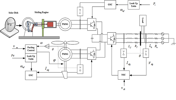
Fig. 3. Structure of simulated system
A-operation concept of Stirling engine (SE)
SE transform energy from heat to mechanical by repeating chain of primary operations, which is known as its closed-cycle, contains a fixed mass of gas called «working fluid», most commonly air, helium or hydrogen. In normal operation, the engine is sealed and no gas enters or leaves the engine [6]. It is hard to figure out that the internally gas is alternately expanding and contracting between them, shifting from the cylinder hot side to the cold side and repeat. Pistons job (dark blue) use the gas expansion energy to turn the machine. Piston's job (green displacer) shuttle the gas from the cylinder hot side to the cold side and repeat [7].
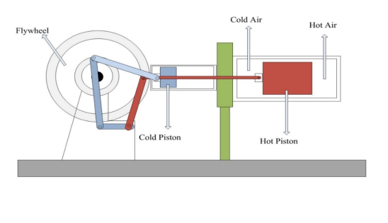
Fig. 4а. Schematic of SE
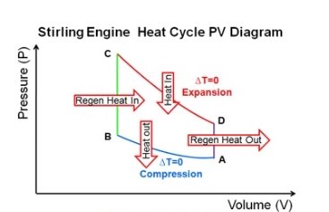
Fig. 4b. SE Heat Cycle
Pistons guaranteed that heat energy shifted from the source to the sink repeatedly and turn to mechanical energy [8].
B-SE modeling
Model SE must be carried out using the relationships that is clarified at this section. The absorber are deem as a heat exporter for the SE. Heat source transports entropy (Sh), through a changing resistance to the air in the cylinder. The heat sink is consideration fixed source of temperature effort (Tc), transfers entropy (Sc), air in roller across a various changing resistance. Air in the roller are modeled like a capacitor in multi-port [9–11].
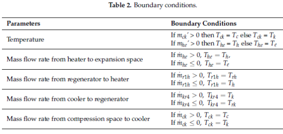
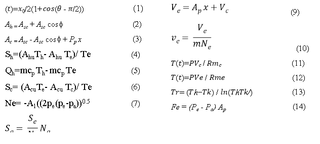 For an exact description of the working gas flow in the work-spaces and heat exchangers. Applied the arithmetic paradigm in Table (2).
2–2 Mode of wind turbine
FAST is thorough software model mechanical component of wind turbine. Wind Turbine formed of various parts which joint together & every part can effect on other parts. Simple model structural are not considered, FAST consider more important wind turbine movements and mechanical models parts like blades, shafts, nacelle, and tower. Versus mechanical software such as ADAMS (Automatic- Dynamic-Analysis of-Mechanical-Systems), little details of the wind turbine movements considers, so less time are needed to do compared with-ADAMS [12].
In this research, the Fatigue, Aerodynamics, Structures, and Turbulence (FAST) is utilized to incarnate an upwind triple blade rotor small horizontal axis wind turbine (HAWT) along with substratum and solid hub. wind turbine degrees of freedoms consist of several parts that include the 1st and 2nd flap-wise, edge-wise mode, blade mode, yaw angle, and tail curl. The Wind Turbine concept of operation is based on the use of the curling control techniques as power control procedure to restrict captivated power at a high wind speed.
This composition allows rotating of the drive train and the rotor around the curving section of the framework on top of the turret whilst tail roll degrees of freedom permits the tail movement around the yawing section of the framework on top of the turret [13–14]. This method cannot be used on higher level wind turbines due to the vast gyroscopic capacity on the wind turbine structure. The aerodynamic moment and the rotor propulsion are managed through regulating the nacelle around the yaw axis in a high wind speed.
The tail curl technique controls the wind turbine rotor as it is lined up measured wind speed with the wind below. In this form, the tail propeller help wind turbine to equilibrium the lateral aerodynamic power. so, Wind Turbine can elicit further power of wind. Curling mechanism rotates the tail propeller that is linked to the back of nacelle side while reverse the balance of the lateral aerodynamic power to preserve wind turbine from the redundant generation of power and the speed of the rotor in a high wind speed [15]. Yaw curl and tail curl axes details as in Fig 5. However, this controller is confirmed and authenticated via test datum of small wind experiment. Curling mechanism controller is built established on a fuzzy logic controller concept where wind speed, shaft speed, and generated power are its inputs.
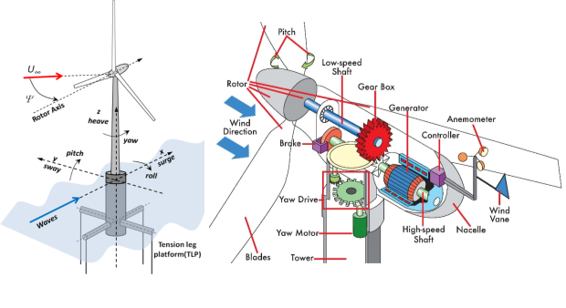
Fig. 5. Side view of tail and details
3. ELECTRICAL PORTIONS
- MODEL PMSG
Using PMSG in the Stirling and Wind Turbine because it is straightforward efficient, simple and without dc provocation voltage via permanent magnets in stator, flux established and supposed sinusoidal. PMSG has modeled employ equations in the reference frame (d-q).
This equations instituted on the stator voltages and currents [16].
Vds= -Ld ((-Lq/ Ld) wr iqs)+ vds*)(15)
Vqs= -Lq ((-Ld/ Lq) wr ids)- (1/ Lq) wr λds)+ vqs*)(16)
 (17)
(17)
 (18)
(18)
![]() (20)
(20)
- Electrical controller scheme
It Consist of these parts
- NSC monitoring
The main purpose of the network side converter (NSC) that is shown in figure 6 is to maintain the voltage of the dc link at steady level. On the other hand, the cascaded control scheme that is built on current network d-q components are used to maintain the injected reactive power to network and dc link voltage. Moreover, q part of network current manage the dc link voltage while, d part manage the reactive power. In regular conditions, reactive power point set at zero to attain unity power factor through the 2nd loop [17–18]. This pattern is achieved through concerning the equations:


Internal loop is purposed on Equations (21) and (22). This controller contains together three- proportional integrals and anti-windup. Proportional integrals controller transfer function has been described in Equation (23)
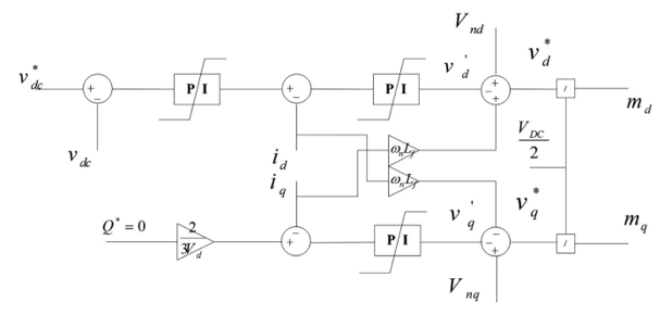
Fig. 6. Network-side converter control scheme
 (23)
(23)
- GSC monitoring
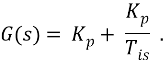
Converter control for the generator side sketched in Fig. 7. Its contain two control loops prepared based on generator static current d-q component and operate independently. 1st loop manage d- component of static current (the d-component of the generator current is normally regulated at zero to reduce static current and power losses). 2nd control loop consist of two cascade (outer, and inner) loops. The outer loop controls shaft speed to maximize the generated power according to reference which is obtained by maximum power point tracking (MPPT). GSC modeled by Eqs. (24–25) which is able to be used in design control current loops:
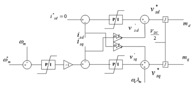
Fig. 7. Generator-side converter control scheme
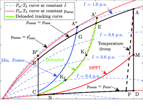
FIG. 8 MPPT curves of Stirling
![]()
![]()
The relationship between the currents and generator voltages in d-q reference frame is revealing in Equations (24) & (25). To regulate generator shaft speed, MPPT achieved for Stirling and Wind Turbine. In this research, power signal feed-back technique used to regulate Stirling and Wind Turbine shaft reference speed such as MPPT. Major concept of this technique is using Stirling and Wind Turbine p, x curves, where p and x are output power and shaft speed. P, and x curves work dependently on Stirling and Wind Turbine ingrained characteristics. Wind Turbine, p, and x curves are attained from Eq-11, but the persistent test is utilized to attain Stirling curve. There is a nonlinear relation between irradiance, output power, and shaft speed.
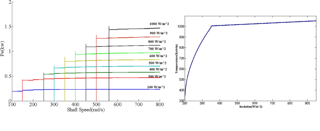
Fig. 9. MPPT curves of Stirling
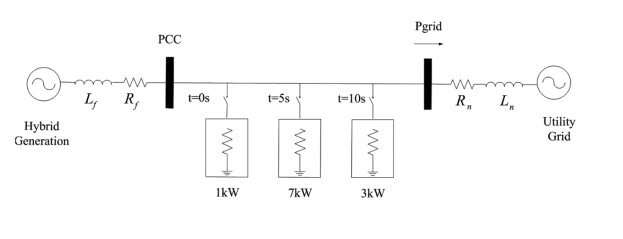
Fig. 10. Screenplay of the load
The SE tested to be at a different shaft speed and different irradiance to define power disposal and get Stirling inherent parameters. Irradiance effect on the temperature, power, and shaft speed seems in fig. 9 and fig. 8. Figure 8 display the extreme power in different radiation happens in 800 rad/s at the shaft speed. Using Eq. (26) to calculate wind turbine reference speed shaft,
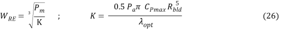
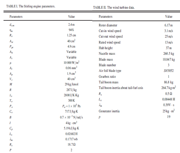
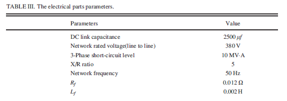
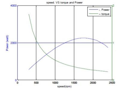
Fig. 11. Output power and mechanical torque versus
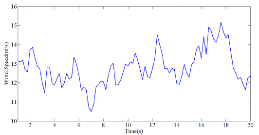
Fig. 12. The wind profile
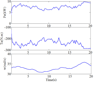
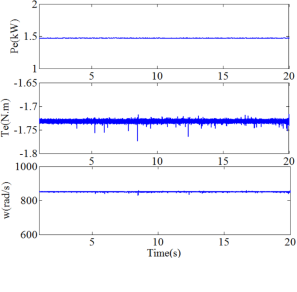
Fig. 13. The shaft speed, power, and torque of WTFig. 14. The shaft speed, power, and torque of SE
4- Simulation result analysis
Hybrid network procedure studied considering load variance, which is seen in the figure 10. An accurate form, contain mechanical, electrical and thermal portions. Simulation allows studying of the interaction with mechanical and electrical parts. Tables’ I–III represents the major information of the wind turbine, generator, and SE parameters. Figure 11 and figure 12
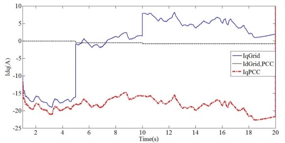
Fig. 15. The d-q currents of hybrid system and grid
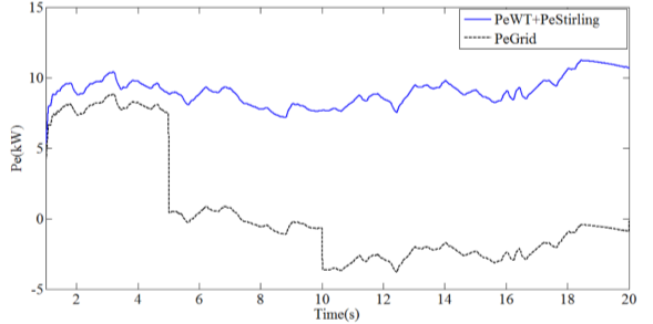
Fig. 16. Power of PCC bus and grid bus
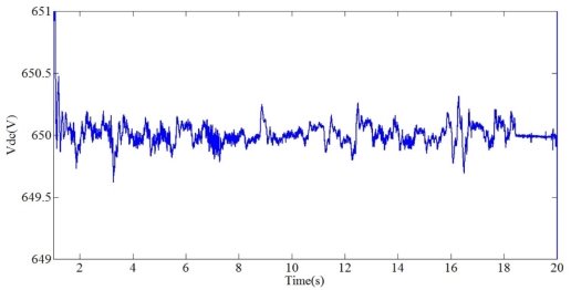
Fig. 17. Dc link voltage
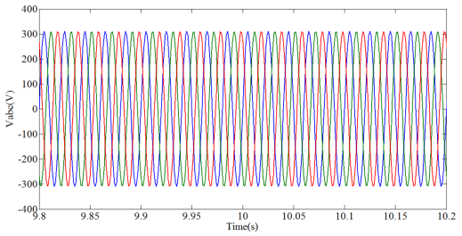
Fig. 18. The network voltage at PCC bus
Figures 13 and 14 show the electrical power, shaft speed, and torque of the Wind Turbine and Stirling. The difference between wind turbine speed shaft and power output is due to wind speed inconstancies. Total outcome of the Stirling and Wind Turbine powers outputs are fed to point of common coupling bus throughout combined Dc link. A study has been done on the effect of the load variance over HS performance, which includes change load in 3 stages. at the first, HS provides and feeds native load with surplus power to Network Utility. At the 5th second, at the power 7 kW, the load in Second case will join with the system. Thus, the power delivered to this network will be minimized. Joining the last one to the grid with 3 kW consumption of power, the grid here provides energy to equip native load. Figure 16 shown the delivered power to utility grid has adverse effect after the time equal 10 seconds. Figure 15 reflects the d — q current ingredients of the HS and grid. q-ingredient of the current grid is tuning at nil through network side converter (NSC) controller. As a result, the power reactive that delivered to the network equal to zero in order to maximize the transfer capacity of active power. Both, Common Coupling bus voltage and link of dc voltage are shown in Fig. 17 and 18. They reflect how Point of Common Coupling voltages and dc link in accepted range while the HS controls constancy in various conditions of load.
5. Conclusion
In summer, this research has studied and structured the HS inclusive the Stirling and Wind Turbine. This system utilized TurbSim and (Fatigue, Aerodynamics, Structures, and Turbulence) to simulate wind turbine direct drive and wind. Additionally, the simulation has utilized for structure electrical controllers and Stirling engine. The controller independently manages real and reactive power. In addition, Dc link voltage remained fixed through a controller as well. The power signal feedback technique was utilized for implementation to maximum power point tracking of the Stirling and Wind Turbine. A response of the system has also estimated under various conditions of the loads, the result of this modern HS will be able to operate like other hybrid systems with excellent efficiency. Precision modeling of electrical and mechanical accessories, which aren't taken into consideration in different works is the feature of this model.
References:
- J. J. Conti, P. D. Holtberg, J. A. Beamon, A. M. Schaal, G. E. Sweetnam, and A. S. Kydes, Annual energy outlook with projections to 2035, report of U. S. Energy Information Administration (EIA), Apr. 2010 [Online]. Available: http://www.eia.doe.gov.
- X. Liu, P. Wang, and P. C. Loh, “A hybrid AC/DC microgrid and its coordination control,” IEEE Trans. Smart Grid 2, 278–286 (2011).
- Genduso, F.; Miceli, R.; Favuzza, S. A perspective on the future of distribution: Smart grids, state of the art, benefits and research plans. Energy Power Eng. 2013, 5, 36–42, doi:10.4236/epe.2013.51005.
-
Абд А. Л. М., Исса Х. А. “Разработка Элементов smart grid для оптимизации режимов районных сетей” ISSN: 2072–0297, Молодой учёный, № 7 (193) / 2018, Feb 28, 2018 С. 117–120.
- Yazdani and R. Iravani, Voltage-Sourced Converters in Power Systems: Modeling, Control, and Applications (John Wiley & Sons, 2010).
- Абд Али Л. М., Исса Х. А. “Hybrid power generation using solar and wind energy” Молодой учёный ISSN: 2072–0297, № 7 (193) / 2018, Feb 28, 2018. С. 19–26.
- Jia, B.; Zuo, Z.; Tian, G.; Feng, H.; Roskilly, A. P. Development and validation of a free-piston engine generator numerical model. Energy Convers. Manag. 2015.
- Yang, Q.; Luo, E.; Dai, W.; Yu, G. Thermoacoustic model of a modified free piston Stirling engine with a thermal buffer tube. Appl. Energy 2012.
- Kraitong, K. Numerical Modelling and Design Optimisation of Stirling Engines for Power Production. Ph.D. Thesis, Northumbria University, Newcastle upon Tyne, UK, 2014.
- Jia, B.; Smallbone, A.; Feng, H.; Tian, G.; Zuo, Z.; Roskilly, A. P. A fast response free-piston engine generator numerical model for control applications. Appl. Energy 2016, 162.
- Aksoy, F, Solmaz, H, Çinar, C, Karabulu, H. 1.2kW beta type Stirling engine with rhombic drive mechanism, international journal of energy research, January 2017, 41:1310–1321
- Thomas, E.; Liu, J.; Goyal, A.; Manuel, L. Long-Term Loads on a Large Offshore Wind Turbine Supported by a Semi-Submersible Platform. In Proceedings of the 34th Wind Energy Symposium, AIAA SciTech Forum, San Diego, CA, USA, 4–8 January 2016.
- Belamadi, R.; Djemili, A.; Ilinca, A.; Mdouki, R. Aerodynamic performance analysis of slotted airfoils for application to wind turbine blades. J. Wind Eng. Ind. Aerodyn. 2016.
- Li S. H., Haskew T. A., Swatloski R. P., & Gathings W. 2012. Optimal and Direct-Current Vector Control of Direct-Driven PMSG Wind Turbines. IEEE Transactions on power electronics, 27, (5).
- Fernandez-gamiz, U.; Zulueta, E.; Boyano, A.; Ansoategui, I.; Uriarte, I. Five Megawatt Wind Turbine Power Output Improvements by Passive Flow Control Devices. Energies 2017, 10, 742.
- Gao, L.; Zhang, H.; Liu, Y.; Han, S. Effects of vortex generators on a blunt trailing-edge airfoil for wind turbines. Renew. Energy 2015.
- Wang, L.;Wang, T.;Wu, J.; Chen, G. Multi-objective differential evolution optimization based on uniform decomposition for wind turbine blade design. Energy 2017, 120, 346–361.
- Asl, M.; Niezrecki, C.; Sherwood, J.; Peter, A. Scaled Composite I-Beams for Subcomponent Testing of Wind Turbine Blades: An Experimental Study. In Mechanics of Composite and Multi-Functional Materials; Springer International Publishing: Munchem, Germany, 2018; pp. 71–78.
