This article focuses on the application of the finite element method for thin elastic plates’ calculation, which is the main purpose of the work. In this paper, by using the finite element method, it was able to fill the gap on the calculation of the plates in the most general formulation, it became possible to take into account the effect on the strain state of the shear plates are not considered by classical theory (Kirchhoff hypothesis). All of these emphasize the originality and relevance of the research topic.
The article sets out the basic provisions of the finite element method, makes deduction of the fundamental dependency of finite element method and calculation formulas, needed for the further calculation of compilation program on the PC.
Key words: plate, deflection, the deflections function, nodal displacements, rod systems, biharmonic equation, the finite element method
Overview of the finite element method
The advantage of the finite element method is comparatively complicated realization on PC with using the software package. Any boundary conditions on the contour of the plate, including elastic, various types of load can be easily set.
The results obtained by using the finite element method were compared with various analytical solutions: classical in trigonometric series, variational and numerical. At the same time finite element method showed acceptable small deviations from the exact solutions obtained by analytical methods, indicating the reliability of the results.
One of the numerical methods for solving problems of solid deformable body mechanics, effectively developing in recent years is the finite element method (FEM). The name of this method to some extent determines its nature: when using the finite element method calculated design is divided mentally into individual elements, which stress-strain state previously studied in detail and can be considered as known. It is assumed that the elements are interconnected in a finite number of points called nodes. At these points forces are determined characterizing the interaction of certain elements or moves through them, in the end stresses and displacements of each element are computed. Thus, the problem is sampled and reduced to solving the system of algebraic equations concerning the unknown force or nodes displacement. Depending on what kind of values are taken as unknown, there are three classical approaches used in the finite element method: force method, displacement method and the mixed method. Want to note that due to a series of advantages, in the finite element method most widely used approach is based on the idea of using the displacement method.
Replacing the original design by setting of discrete elements unifies the calculation of various building objects: rod systems, thin-walled and massive structures and the real structures, in which rods, plates, shells, arrays, etc. are combined. It makes the finite element method is very versatile and explains its increased popularity.
Depending on the type of considered construction the type of finite element is determined. As the final element for the rod systems can be rods with various fixed at the ends, which are the members of nodes. Thin-walled spatial systems consisting of plates and shells are divided into triangular, rectangular or elements of any other shape with nodes at the corner points. Further we will dwell on the consideration of rectangular finite elements and their using in calculations of plates.

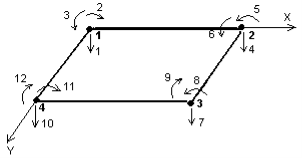
Fig. 1. Rectangular finite element isolated from the plate
Taking unknown potential movement of the element nodes as a basic, let's call their quantity the degree of freedom of the element (the local degree of freedom). We can see that in the problem of bending the rectangular plate finite element isolated from the plate (Figure 1.1), will have 12 degrees of freedom, since each node has vertical deflection and two rotation angle along the coordinate axes.
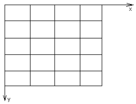
The finite element method is assumed to apply nodal forces to element acting in the direction of possible displacements of its nodes. Linking the forces with the movements of the element node, i.e. obtaining the matrix hardness of K-element, characterizing its elastic properties, it is one of the main stages of the finite element method. For this purpose, as a rule, it is necessary to consider three groups of equations: static, describing an equilibrium conditions of the element, geometric, establishing a link between its deformations and displacements, and physical, relating the stress to strain. Next, when the matrix stiffness of each element is formed, the construction of a total matrix stiffness of the entire plate is made, considering the dock of the elements in the nodes. In other words, in order to calculate the plate, first you must break it by the grid of the finite elements, number nodes of elements and all movements, study stress-strain state of each element and then proceed to the calculation of the whole plate. Then we will obtain the required parameters in the nodes of the plate. Figure 1.2 shows an example of the plate with coated grid of the finite elements. Consider all of the above in details.

Fig. 2. Example of the plate is coated by the grid of the finite elements
Deflections’ function of the finite element which shape is rectangular
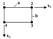
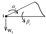
Select the finite element (Figure 3) from the plate (Figure 2) and consider it in the local coordinate system. Enumerate nodes in series (round, clockwise from the top left node). The deformed state is completely determined by the nodal displacements. Thus, for a random node (Figure 4) we have three movements ![]()

Fig. 3. Rectangular finite element

Fig. 4. The degree of freedom of the i-th node
These angular movements are defined by the partial derivatives of deflections' functions W(x,y):
![]() ,
, ![]() . (1)
. (1)
To determine the function of deflections of the finite elements we will use an equilibrium equation
![]() ,
,
and in the absence of external load we obtain:
 (2)
(2)
Its solution will be sought in the form of:
W(x,y) = X(x)Y(y).(3)
By introducing (3) to (2) we obtain the equation of the form:
![]()
which is split into three independent equations:
![]() (4)
(4)
The first and the third equations are equations of bending of perpendicular beams. Their decisions in coordinate functions are of the form:
X(x)= f1 (x) Xi +f2 (x)![]() +f3 (x) Xj + f4 (x)
+f3 (x) Xj + f4 (x)![]() ,
,
Y(y)= φ1 (y) Yk +φ2 (y)![]() + φ3 (y) Ym + φ4 (y)
+ φ3 (y) Ym + φ4 (y)![]() , (5)
, (5)
f1(x) = 2x3–3x2 +1, φ1(y) = 2y3–3y2 +1, ![]() =
=![]() a,
a,
f2(x) = x3–2x2 +x, φ2(y) = y3–2y2 + y, ![]() =
=![]() a,
a,
f3(x) = 3x2 –2x3, φ3(y) = 3y2–2y3, ![]() =
=![]() b,
b,
f4(x) = x3 — x2, φ4(y) = y3 — y2, ![]() =
=![]() b,
b,
Where ![]() ,
, ![]() , x, y — dimensionless coordinates; i, j, k, m — beam nodes; Xi, Xj, Yk, Ym — vertical displacements;
, x, y — dimensionless coordinates; i, j, k, m — beam nodes; Xi, Xj, Yk, Ym — vertical displacements;![]() — angular displacements of the required beams; f1(x)– f4(x), φ1(y)– φ4(y) — coordinate functions in bending beams. By substituting (5) in (3) let’s write the function of deflections of the finite elements in this form:
— angular displacements of the required beams; f1(x)– f4(x), φ1(y)– φ4(y) — coordinate functions in bending beams. By substituting (5) in (3) let’s write the function of deflections of the finite elements in this form:
![]()
![]() (6)
(6)
![]()
![]() +
+![]() ,
,
where new random constants are:
![]() = Xi Yk,
= Xi Yk, ![]() = Xi
= Xi ![]() ,
, ![]() = Xi Ym,
= Xi Ym, ![]() = Xi
= Xi ![]() ,
,
![]() =
= ![]() Yk,
Yk, ![]() =
= ![]() ,
, ![]() =
= ![]() Ym,
Ym,![]() =
= ![]() ,
,
![]() = Xj Yk,
= Xj Yk, ![]() = Xj
= Xj ![]() ,
, ![]() = Xj Ym,
= Xj Ym, ![]() = Xj
= Xj ![]() ,
,
![]() =
= ![]() Yk,
Yk, ![]() =
= ![]() ,
,![]() =
= ![]() Ym,
Ym,![]() =
= ![]() . (7)
. (7)
New known functions are:
F11 = f1(x)φ1(y), F12 = f1(x)φ2(y), F13 = f1(x)φ3(y), F14 = f1(x)φ4(y),
F21 = f2(x)φ1(y), F22 = f2(x)φ2(y), F23 = f2(x)φ3(y), F24 = f2(x)φ4(y),
F31 = f3(x)φ1(y), F32 = f3(x)φ2(y), F33 = f3(x)φ3(y), F34 = f3(x)φ4(y),
F41 = f4(x)φ1(y), F42 = f4(x)φ2(y), F43 = f4(x)φ3(y), F44 = f4(x)φ4(y). (8)
The boundary conditions of the finite elements (Figure 2) are following:
W(0, 0) = W1,α(0, 0) = ![]() , β(0, 0) =
, β(0, 0) = ![]() ,
,
W(1, 0) = W2,α(1, 0) = ![]() , β(1, 0) =
, β(1, 0) = ![]() ,
,
W(1, 1) = W3,α(1, 1) = ![]() , β(1, 1) =
, β(1, 1) = ![]() ,
,
W(0, 1) = W4, α(0, 1) = ![]() , β(0, 1) =
, β(0, 1) = ![]() , (9)
, (9)
where W(0, 1) — the value of the deflections’ function in the 4th node; α(1, 0) — the value of the first derivative (1) in the second node; β(0, 1) — the value of the derivative (1) in the 3rd node; W1 — W4 — linear movements of the finite elements; ![]() — angular displacements of the nodes along the axe X;
— angular displacements of the nodes along the axe X; ![]() — angular displacements of finite elements nodes along the axe Y.
— angular displacements of finite elements nodes along the axe Y.
Determined derivatives' (1) of the function (6) and substituting them alternately in (9) we have the values of the random constants:
![]() =
= ![]() ,
, ![]() =
= ![]() a,
a, ![]() =
= ![]() b,
b,
![]() =
= ![]() ,
, ![]() =
= ![]() a,
a, ![]() =
= ![]() b,
b,
![]() =
= ![]() ,
, ![]() =
= ![]() a,
a, ![]() =
= ![]() b,
b,
![]() =
= ![]() ,
, ![]() =
= ![]() a,
a, ![]() =
= ![]() b. (10)
b. (10)
Thus, twelve from sixteen random constants are determined by a simple way, from the boundary conditions. To determine the remaining random constants we use the second equation (4) and represent it in the form of:
![]() =
= ![]() .(11)
.(11)
For this, we write the following boundary conditions at the nodes of the finite element:
![]() = 0,
= 0,![]() = 0,
= 0,![]() = 0,
= 0,![]() = 0(12)
= 0(12)
Determined the second derivatives of (5) and calculated their product by (11), and then substituted into (12), after a reduction for 4 following system of equations we obtain:
![]() ,
,
![]() ,
,
![]() ,
,
![]() . (13)
. (13)
Where free members are expressed through terms of known coefficients (10) take the following values:
![]() ,
,
![]() ,
,
![]() ,
,
![]() (14)
(14)
After the solving of equations system (13), we find the remaining random constants:
![]() ,
,
![]() ,
,
![]() ,
,
![]() . (15)
. (15)
By introducing them in (6) we have the function of deflections of the finite element which shape is rectangular:
W(x, y) ![]() (x, y)+
(x, y)+![]() (x, y) +
(x, y) +![]() (x, y)+
(x, y)+![]() (x, y) +
(x, y) +
+![]() (x, y) +
(x, y) + ![]() (x, y) +
(x, y) +![]() (x, y)+
(x, y)+![]() (x, y) +
(x, y) +
+ ![]() (x, y) +
(x, y) + ![]() (x, y) +
(x, y) +![]() (x, y)+
(x, y)+![]() (x, y) (16)
(x, y) (16)
![]() (x, y)=
(x, y)=![]() ,
, ![]() (x, y)=
(x, y)=![]() ,
,
![]() (x, y)=
(x, y)=![]() ,
, ![]() (x, y)=
(x, y)=![]() ,
,
![]() (x, y)=
(x, y)=![]() ,
,![]() (x, y)=
(x, y)=![]() ,
,
![]() (x, y)=
(x, y)=![]() ,
, ![]() (x, y)=
(x, y)=![]() ,
,
![]() (x, y)=
(x, y)=![]() ,
, ![]() (x, y)=
(x, y)=![]() ,
,
![]() (x, y)=
(x, y)=![]() ,
, ![]() (x, y)=
(x, y)=![]() . (17)
. (17)
Where the functions ![]() are still determined by the formula (8).
are still determined by the formula (8).
Considering values of beam functions (5) and random constants (10), we write the finite element's function of deflection in standard form:
![]() ,(18)
,(18)
![]() ,
,
![]() .
.
Therein ![]() - transposed vector of plate coordinate functions;
- transposed vector of plate coordinate functions; ![]() - vector of the finite elements’ nodal displacements.
- vector of the finite elements’ nodal displacements.
Plate coordinate functions are:
![]() ,
,
![]() ,
,
![]() ,
,
![]() ,
,
![]() ,
,
![]() ,
,
![]() ,
,
![]() ,
,
![]() ,
,
![]() ,
,
![]() ,
,
![]() , (19)
, (19)
![]() ,
, ![]() ,
, ![]() ,
,
![]() ,
, ![]() ,
, ![]() ,
,
therein ![]() ,
,![]() ,
,![]() - rod's coordinate functions in torsion.
- rod's coordinate functions in torsion.
Analysis of the formula (19) shows that the coordinate functions of the finite element of plate are equal to the product of the coordinate functions of the beam in bending and coordinate function of the rod in torsion. Each coordinate function describes the finite elements deformation caused by the unit value of the node displacement. For example, ![]() is the finite elements bending form which shape is rectangular, caused by the unit value of the angular displacement
is the finite elements bending form which shape is rectangular, caused by the unit value of the angular displacement ![]() .
.
Thus, the method is based on the general solution of the biharmonic equation (2) gives a deflection function of the finite elements explicitly and gives it a physical meaning; introduce plate's the finite elements deformation through the beam and rod deformation. It is significant that the function of the finite elements deflection (18) is the basis for calculating the plate by the finite elements method. On its base it's easy to develop a calculation algorithm with implementation on PC.
References:
- Рикардс Р. Б. Метод конечных элементов в теории оболочек и пластин. — Рига: «Зинатне», 1988. — С. 54–58.
- Вайнберг Д. В., Вайнберг Е. Д. Расчёт пластин. — Киев: Будивельник, 1970. — 320 с.
- Ahanova A. S., Yessenbayeva G. A., Tursyngaliev N. K. On the calculation of plates by the series representation of the deflection function. — Bulletin of the Karaganda University. Mathematics Series. 2016. — № 2(82). — P. 15–22.

