


Abstract.Needs for investigating underwater flora, fauna, and mineral resources, as well as rescue machines stimulate creation of remotely operated vehicles. Majority of them and surface vessels are using propellers for propulsion and maneuvering. Propellers, the effective thrusters for straightforward motion, create operational difficulties in turning and positioning. In this work, an attempt to create a universal jet propulsion model as an alternative for small autonomous underwater vehicles is undertaken. The mechanism of motion of the vehicle is considered. The rotating nozzle is designed and the controller is developed to control speed for certain vehicle geometries. The uniform circular motion of the robot in horizontal plane is analyzed. Simulink and SimMechanics models show a good agreement with the calculated parameters. The model can be easily resized and reequipped for the different tasks and developed for either tethered or autonomous use. It suggests several advantages such as an improved drag profile, by diminishing protruding parts; reduced power consumption, due to avoiding the production of vortices perpendicular to the direction of motion as compared with the propeller systems; created extra propulsion force, owing to sucking water for ejecting directly from the frontal part; maneuverability in enclosed areas and diminished risk of injuring and killing sea creatures. The further plans are developing a remote control system and implementation.
Index terms: underwater, robotics, propulsion, control.
- Introduction. Currently thousands of robotic undersea vehicles are in regular operation worldwide [1]. The domain of underwater robotics is intended to grow rapidly, and the time when autonomous marine vehicles will freely roam the ocean is imminent [2]. Development of underwater robotic devices is motivated by the high cost of human divers and the risk to life of working under water. Today, underwater vehicles are widely used in science, ocean mining, oil exploration and production, environmental control and monitoring, underwater archeology, search and rescue missions, maintenance/monitoring of underwater structures, and for structural investigation of dams and floors of water-storage basins, man-made lakes and ponds. Underwater robots help us better understand marine and other environmental issues, protect the ocean resources of the earth from pollution, and efficiently utilize those resources for human welfare [3,4,5].
The wide range of applications for underwater vehicles (UVs) promotes design differentiation. Two main categories of unmanned underwater-vehicles are: autonomous underwater vehicles (AUVs) and remotely operated vehicles (ROVs). AUVs must operate for relatively long periods underwater without direct human guidance, and ROVs are powered and remotely operated via a tether connected to a surface command ship [4]. Though both AUVs and ROVs are distinguished by shortcomings and advantages, there is one generality for them: most of the existing systems use propellers for their propulsion.
Traditional propeller-type thrusters are very efficient when operating at nominal rotation rates. However, accurate positioning often requires short impulses, which correspond to propeller rotations on the order of single rotations that can result in unpredictable control forces. This coupled with the unpredictability of the environment causes traditional propeller-type thrusters to be non-ideal for accurate maneuvers [6]. Efficiency of propellers designed for small underwater vehicles are no more than 40 percent. The main cause is the production of vortices perpendicular to the direction of motion. Due to their orientation, these vortices do not produce thrust, though they increase power consumption [7, 8]. The propellers as protruding parts create extra drag forces, inconveniences in maneuvering, can damage and kill sea animals, and can easily become entangled in underwater vegetation or cabling. In the light of above discussion, the jet propulsion model was suggested in this work. The rest of this paper is organized as follows: section II describes related works; the underwater robot model and equations of motion are presented in section III; section IV presents the simulation details for straightforward and circular motions; section V provides conclusions and future work, and the last section presents the references.
2. Related work. Some alternative forms of propulsion have been developed to get around the deficiencies of propeller type thrusters. One of them is inspired by the natural locomotion of squid. By this method low momentum fluid is ingested into a cavity (known as the mantle for squid), and subsequently ejected with a much higher momentum through an orifice. The high momentum fluid rolls into a vortex ring, and carries the momentum away from the animal. The resulting momentum transfer propels the squid forward [4]. The compact zero-mass pulsatile jet technology proposed therein, could overcome shortcomings described above for low speed maneuvering of AUVs and ROVs, and enable new types of lower-cost AUVs.
In the pulsed jet, an ejected mass of fluid rolls into a toroidal vortex ring which moves away from its source. At high pulsing frequency, the jet structure can become increasingly turbulent. This propulsion scheme has no protruding components that increase drag, has very few moving parts, and takes up relatively little volume. A hybrid design, which incorporates both a main propeller and a distributed set of pulsatile jets, will improve low speed AUV performance. While propellers clearly perform best at cruising speeds, pulsatile jets can significantly augment low speed maneuverability, and enable occasional loitering/hovering actions. Moreover, a pulsed jet can give rise to a greater average thrust than a steady jet of equivalent mass flow rate [4, 9]. A fish-like propulsion system, the small autonomous robotic vehicle driven by an oscillating foil, suggests as an interesting and efficient alternative to propellers in small UVs [7]. Direct force and power measurements performed on a streamlined, fish-like, flexible-hull vehicle with turbulence stimulation, showed that the drag on the actively swimming body is smaller than the drag on the same body towed straight and rigid [10].
Another solution of the problem developed is an aquatic walking robot – AQUA. Through an appropriate design of limbs for the vehicle, its legs can be used both for traditional walking locomotion strategies (either on land, or along the bottom of the aquatic environment), as well as to propel the vehicle through the water by swimming [11].
An intent to imitate sea and ground creatures in developing underwater vehicles can be seen from above; thus imitating the high speed, maneuverability and minimum energy expenditure of those creatures. A great deal of progress has been made in biorobotic studies of locomotion, orientation, and vertebrate arm control [12]. The vehicle, presented in [13], proposes to propel by means of four pump units based on the Downingtown–Huber flexible-tube design with eccentric rotors. Comparison of this jet-propulsion system with the conventional screw-type propulsion via simulation would suggest that latter performs marginally better than the former, at least as far as horizontal straight-line motion concerned.
The model of underwater vehicle, suggested by present paper, uses a jet propulsion system. It moves by pump engine fixed at the geometrical center of the vehicle. Jet propulsion takes place by injecting water in the front part of the vehicle and subsequent ejecting it at the rear part through a nozzle.
3. Equation of motion. The CAD model of the underwater robot is shown in Fig. 1. A pump located at the geometrical center sucks water in at the front through the lattice and ejects that water under higher pressure. The robot moves forward due to difference of pressure between the front and rear parts of the vehicle. Sucking water directly at the front creates extra propulsion force because of decreasing the pressure to compare with the rear. The nozzle can turn up to 90 degrees to the right and left by the worm gear, driven via the electric motor. Water entry into inner part of the vehicle from the ejecting tube and from the environment is excluded using two elastically sealing bellows.
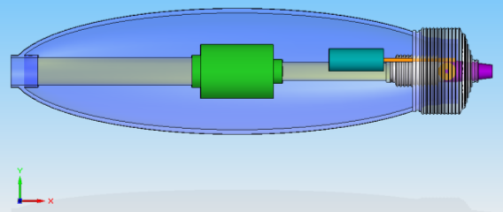
Fig. 1. Top view of the CAD of the underwater vehicle.
Governing equations of rigid body motion are described in [14, 15]. Briefly, the motion of a rigid body, expressed as the translation of its center of mass and rotation about the center of mass, decouple into the following two vector equations:
![]() (1)
(1)
![]() (2)
(2)
where F is the sum of applied forces, M,![]() and
and ![]() are the mass, velocity and acceleration the of the body respectively,
are the mass, velocity and acceleration the of the body respectively,![]() is the moment and h is the angular momentum.
is the moment and h is the angular momentum.
In general, the mathematical expressions of a rigid body motion include components associated with the weight of the vehicle, lift effect, added mass, drag and Coriolis effects. Here, for the preliminary approach, we take some simplifications. First, we assume that the vehicle is fully submerged and fully buoyant and can stay motionlessly at certain depth in immobile water. This will afford neglect weight of the vehicle and lift effect. Second, it may be assumed that there are no fluid particles moved with the vehicle and deflection of the vehicle from its path, due to constant and small enough desired velocity of the robot. Thus we can neglect added mass and Coriolis effects. Third, assuming that the density is the same within full volume, occupied by robot, we can guess that the centers of mass and buoyancy are coincide and located at the geometric center of the robot frame. These assumptions allow us neglect the moment components and we are dealing with thrust ![]() and drag
and drag ![]() forces only:
forces only:
![]() (3)
(3)
According to D’Alembert’s paradox [16], the uniform motion of the body of any shape in the ideal incompressible fluid should occur without head resistance:![]() But in viscous medium the drag force comes into existence [2, 13, 17]:
But in viscous medium the drag force comes into existence [2, 13, 17]:
![]() (4)
(4)
where ![]() is the drag coefficient,
is the drag coefficient,![]() is the velocity of the body relative to immobile water in direction of motion,
is the velocity of the body relative to immobile water in direction of motion,![]() is the water density, and
is the water density, and ![]() is the projected area of the vehicle perpendicularly to the direction of motion. However, at low velocities, when fluid motion is laminar, the drag follows a linear relation with speed [19]. Likewise Stokes stated that at small velocities and dimensions of the body (at small Reynolds' numbers,
is the projected area of the vehicle perpendicularly to the direction of motion. However, at low velocities, when fluid motion is laminar, the drag follows a linear relation with speed [19]. Likewise Stokes stated that at small velocities and dimensions of the body (at small Reynolds' numbers,![]() , when the resistance of the medium is stipulated by friction forces only) the drag force can be defined as [16]:
, when the resistance of the medium is stipulated by friction forces only) the drag force can be defined as [16]:
Where ![]() is the coefficient of proportionality which depends on the shape of the body,
is the coefficient of proportionality which depends on the shape of the body,![]() is the dynamic viscosity of the medium and
is the dynamic viscosity of the medium and ![]() is the characteristic dimension of the body. We can write (5) as
is the characteristic dimension of the body. We can write (5) as ![]() if
if ![]() The thrust force generated by vehicle can be expressed as
The thrust force generated by vehicle can be expressed as
![]() (6) and
(6) and
![]() (7)
(7)
where ![]() is the mass flow rate,
is the mass flow rate, ![]() is the velocity of ejected water,
is the velocity of ejected water, ![]() is the volume flow rate and
is the volume flow rate and ![]() is the inner diameter of the nozzle. Now (3) can be modified:
is the inner diameter of the nozzle. Now (3) can be modified:
![]() (8)
(8)
The accepted geometrical parameters of the vehicle under consideration are: the total length 532 mm, the maximal outer diameter 140 mm, the inner diameter of the nozzle 10 mm and the mass is 12 kg. The output flow rate of the pump assumed to be ![]() The output velocity of the water and thrust force, taking into account the density of water
The output velocity of the water and thrust force, taking into account the density of water ![]() can be calculated using (7) and (6):
can be calculated using (7) and (6): ![]() and
and ![]() The maximal steady state velocity in straight forward direction can be evaluated using (4):
The maximal steady state velocity in straight forward direction can be evaluated using (4): ![]() where
where ![]() in consideration the ratio of the length
in consideration the ratio of the length ![]() to the diameter
to the diameter ![]() of the vehicle
of the vehicle ![]() [18] and
[18] and ![]()
The solution of (8) is
![]() (9)
(9)
So, we have ![]()
![]() and
and ![]() This solution can be compared with the step response of the vehicle. The transfer function of the latter can be obtained easily from (8):
This solution can be compared with the step response of the vehicle. The transfer function of the latter can be obtained easily from (8):
![]() (10)
(10)
and
 (11)
(11)
Fig. 2 presents the theoretical evolution of the velocity over time according to solution (9) and the step response (reduced to the velocity) of the vehicle obtained by Matlab.
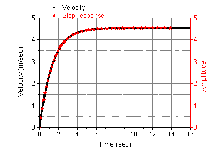
Fig. 2. Analytical solution of (8) and the step response of the vehicle reduced to the velocity
4. Simulation. A) Straightforward motion. The Fig. 3 shows the block diagram of the vehicle with the controller. We choose the PI controller and define its parameters.
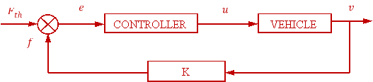
Fig. 3. The closed loop block diagram of the vehicle with the controller
Using transfer function of the vehicle (11) and PI controller,
![]() , (12)
, (12)
where KP and KI are coefficients of proportionality of the proportional and integral components of the controller respectively, the transfer function of the closed loop system can be derived easily:
 (13)
(13)
Comparing characteristic polynomial from (13) to the second order normalized one
![]() , (14)
, (14)
Where ![]() is the dimensionless damping ratio and
is the dimensionless damping ratio and ![]() is the natural frequency, it can be defined controller parameters. If require
is the natural frequency, it can be defined controller parameters. If require ![]() =1 (critical damping, where is no overshoot), the region without overshoot process lies between values of
=1 (critical damping, where is no overshoot), the region without overshoot process lies between values of ![]() 1 and 1.8 in step response of the PI controller as it shown in Fig. 4. The fastest (with a negligible overshoot) case occurs when
1 and 1.8 in step response of the PI controller as it shown in Fig. 4. The fastest (with a negligible overshoot) case occurs when ![]() =1.4 within 2% deviation. The settling time 1.35 seconds, and the controller parameters are: Kp=2.698 and KI=2.589.
=1.4 within 2% deviation. The settling time 1.35 seconds, and the controller parameters are: Kp=2.698 and KI=2.589.
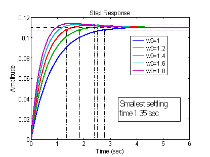
Fig. 4. Step response of the vehicle for different values of ![]()
According to the block diagram (see Fig. 3), the equation of the vehicle with the controller can be written as
![]() (15)
(15)
and derivative:
![]() (16)
(16)
Alternatively, the last expression can be obtained from (13) also. The analytical solution of (16), substituting known values and letting ![]() , and the simulation results with the controller chosen are presented in Fig. 5.
, and the simulation results with the controller chosen are presented in Fig. 5.
One can see that the analytical solution gives the better result. Though, practically it is possible reach the same or even better results manipulating the controller parameters during simulation, in terms of real implementation possibilities and requirements for our vehicle, we chose the presented parameters for the controller.
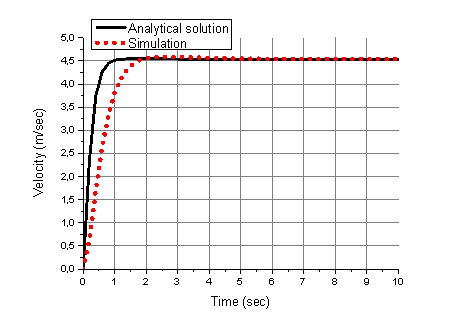
Fig. 5. The Matlab solution of (13) and simulation results with the PI controller
B) Uniform circular motion in horizontal plane. Recall that the nozzle, mounted at rear part, can provide turning of the robot to right and left by turning itself in ±90 degrees in horizontal plane relative to longitudinal axle through-passed in direction of motion. The sketch, provided in Fig. 6, illustrates the circular motion of the vehicle subject to such angle . The values of centrifugal and tangential forces, and the radius are shown for the angle between the nozzle and the longitudinal axis equal to =54degrees.
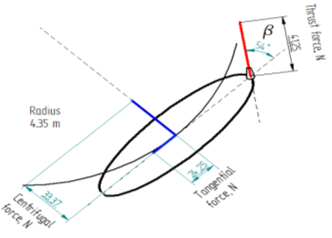
Fig. 6. Sketch of circular motion of the vehicle for the angle between the nozzle and the longitudinal axle, , is equal to 54 degrees
When the nozzle is turned for angle relative to the longitudinal axis of the vehicle, the tangential and normal components are defined as
![]() . (17)
. (17)
In the other hand,
 .(18)
.(18)
The linear ![]() and angular
and angular ![]() velocities, the radius of uniform circular motion R and the revolution period T can be defined for any angle:
velocities, the radius of uniform circular motion R and the revolution period T can be defined for any angle:
 . (19)
The Fig. 7 illustrates the linear and angular velocities, radius of circular motion and revolution period as function of turning angle.
a) 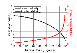 b)
b) 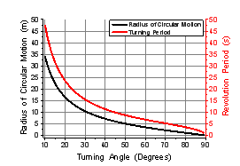
Fig. 7. The linear and angular velocity (a) and radius of circular motion and revolution period (b) as the function of the turning angle of the nozzle in XY plane
Overall, the circular motion of the vehicle is stipulated by two forces:
 (20)
(20)
where FX(t) and FY(t), ![]() and
and ![]() are the forces and accelerations in X and Y directions respectively,
are the forces and accelerations in X and Y directions respectively, ![]() is the radius of the circle and
is the radius of the circle and ![]() is the initial angular position of the vehicle relative to axis of motion. Signs of minus are the results of twice derivatives. Here we can assume initial conditions to be zero:
is the initial angular position of the vehicle relative to axis of motion. Signs of minus are the results of twice derivatives. Here we can assume initial conditions to be zero: ![]() =0 that is the nozzle holds the position parallel to the central longitudinal axis of the vehicle. The thrust force is spent to move the robot in straightforward direction. If the nozzle turns to the right or left, this force is split into two FX(t) and FY(t) parts and the ratio of which will appoint the radius of the circle and the angular velocity.
=0 that is the nozzle holds the position parallel to the central longitudinal axis of the vehicle. The thrust force is spent to move the robot in straightforward direction. If the nozzle turns to the right or left, this force is split into two FX(t) and FY(t) parts and the ratio of which will appoint the radius of the circle and the angular velocity.
The animation picture of circular motion and trace, constructed by 6DoF (Euler Angles), are shown in the Fig.8. The simulation was performed using the coordinates of the center of mass of the vehicle in XY plane:
![]() , (21)
, (21)
and velocity
 . (22)
Taking derivative of the velocity and multiplying by m we get forces acting in X and Y directions:
 3)
3)
The assumed value of turning angle of the nozzle relative to the longitudinal axle of the vehicle was = 85 degrees. The corresponding values of the angular velocity and radius of circular motion are ![]() and
and ![]() respectively. Disturbances assumed to be zero. Decrease in turning angle, , will lead to increase in turning radius. It is worth to note that the latter will not change by increasing the thrust force,
respectively. Disturbances assumed to be zero. Decrease in turning angle, , will lead to increase in turning radius. It is worth to note that the latter will not change by increasing the thrust force, ![]() , though, the linear and angular velocities will increase according to (19).
, though, the linear and angular velocities will increase according to (19).
The SimMechanics model was tested for turning angle = 65 degrees. The values of the angular velocity and the radius were ![]() and
and ![]() respectively. The results obtained in both Simulink and SimMechanics models show a good agreement with the results presented in Fig. 7.
respectively. The results obtained in both Simulink and SimMechanics models show a good agreement with the results presented in Fig. 7.
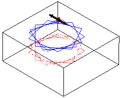
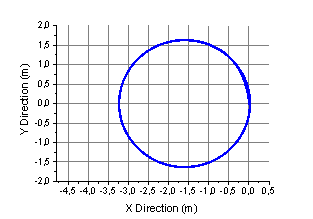
Fig. 8. The Matlab animation picture and trace, constructed using data from animation results
5. Conclusion and future work. The CAD model of the underwater robot is presented and the mechanism of motion is developed. The PI controller is chosen for speed control and its parameters are defined. The uniform circular motion of the robot in horizontal plane analyzed. The centripetal force, angular velocity, circle radius and revolution period are investigated as a function of the turning angle of the nozzle for low speed maneuvering. The Simulink and SimMechanics simulations are performed. The results obtained in both models show a good agreement with the calculated parameters.
The model suggests several advantages such as an improved drag profile, due to propulsion system without protruding parts; reduced power consumption, by avoiding the production of vortices perpendicular to the direction of motion as compared with the propeller systems; maneuverability in enclosed areas; diminished risk of injuring and killing sea creatures. An extra propulsion force will be created by sucking water for ejecting directly from the frontal part. The robot, with small size and a good performance can be a useful and universal machine for underwater investigations and rescue operations. It can be equipped with the different devices for different tasks, resized and developed for tethered or autonomous use.
With a glance aforesaid, the future plans are:
1. Chose the motors and implementation of the electronic PI controller.
2. Development of a remote control system.
4. Supply the robot with the needed apparatus for underwater investigations.
References:
- Louis L. Whitcomb, “Underwater Robotics: Out of the Research Laboratory and Into the Field”. Preprint of an invited paper to appear in the Special Session on Industrial Robotics. IEEE 2000 International Conference on Robotics and Automation. [Electronic version]. Retrieved April 12, 2012 from citeseerx.ist.psu.edu/viewdoc/download?doi=10.1.1.31.5434&rep=rep1&type=pdf
- Lapierre Lionel, “Underwater Robots Part II: Existing Solutions and Open Issues.” Published on: 2006-12-01. [Electronic version]. Retrieved April 12, 2012 from www.intechopen.com/redirector/articles/underwater_robots_part_ii__existing_solutions_and_open_issues
|
- K. Mohseni. Zero-mass pulsatile jets for unmanned underwater vehicle maneuvering. AIAA 2004-6386. [Electronic version]. Retrieved April 12, 2012 from citeseerx.ist.psu.edu/viewdoc/download?doi=10.1.1.136.7220&rep=rep1&type=pdf
- Richard M. Murray, Zexiang Li and S. Shankar Sastry, A Mathematical Introduction to Robotic Manipulation. Page 397, 1994, CRC Press. [Electronic version]. Retrieved April 12, 2012 from www.cds.caltech.edu/~murray/books/MLS/pdf/mls94-complete.pdf
- Michael Krieg, Student Member, IEEE , and Kamran Mohseni, Member, IEEE. Dynamic Modeling and Control of Biologically Inspired Vortex Ring Thrusters for Underwater Robot Locomotion.[Electronic version]. Retrieved April 12, 2012 from http://enstrophy.mae.ufl.edu/~mohseni/PSpdf/MyPapers/IEEETransRobotics2010VRT.pdf
