


A soil pipe canal (figure 1) has been applied for implementation of research of the process of soil cutting, that consists of a reinforced concrete tank 1 with rectangular cross-section which, in its turn, is filled with soil 7. A track of rails 2 is mounted on bracket supports along the soil pipe canal. The soil pipe canal is equipped with the equipment of upper and lower soil damping system within the environment close to field conditions. A traveling cart 3, on the bottom of which a moling ripper is fixed, is mounted on the track of rails. The cart is traveling by means of a multiple-speed winch rope 6. For gaging of effort of cutting on cable the dynamometer 8 is established. The winch 5 is composed of a three-speed engine 9, a gearbox of ZIL-130 vehicle 10, a redactor 11 and a drum 12. The winch can arrange the reverse traveling of the cart (in 18 positions).
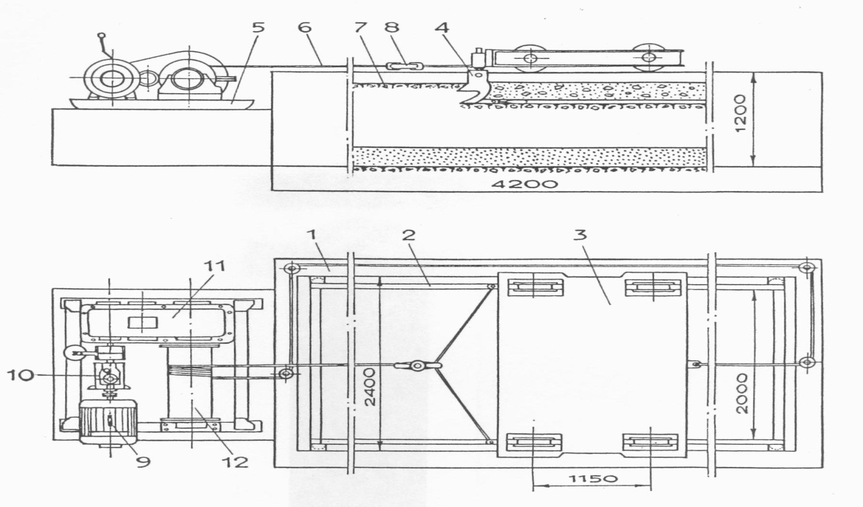

Figure 1. Design map of soil pipe canal and mole draining device
1-reinforced concrete tank; 2-track of rails; 3-traveling cart; 4-moling ripper; 5-towing winch; 6-rope; 7-clay soil; 8-dynamometer; 9-towing winch engine; 10-gearbox; 11-reductor; 12-drum.
Technical characteristics of soil pipe canal
The table
|
Description of parameters |
Unit measure |
Parameters |
|
Length |
m |
42 |
|
Clear width |
m |
2,4 |
|
Depth |
m |
1,2 |
|
Width of rail track |
m |
2,0 |
|
Stroke length of service cart |
m |
37 |
|
Speed of service cart |
m/min |
6-24 |
|
Maximum towing capacity of cart |
N |
37500 |
|
Maximum towing capacity of winch |
N |
37500 |
|
Speed of rope |
m/min |
24-30 |
|
Power of engine |
kW |
15 |
|
Weight of traveling cart |
kg |
2500 |
In course of preparation of soil pipe canal the soil is brought to homogenous state by means of leveling, damping and consolidation of soil. In order to bring the soil to homogenous state its preliminary ripping within the whole width of soil pipe canal is carried out as well. To realize this task teeth of the ripper are set to maximum depth and later, successive traveling of cart with its ripper lowered is initiated until homogenous soil with no clots is formed. Required damping of soil is carried out in course of ripping by means of delivery of water through the damping system with the cart traveling at constant speed.
With the view of precise definition of soil dampness soil samples are selected in three points along the width of the soil pipe canal and at interval of each 3 meters along its length. Thus, in course of successive traveling of the cart, soil is to be leveled by dumping. After that the soil is consolidated by mechanical sealing, and consistency of the soil is measured by means of standard plunger DorNII. Upon completion of ground surface preparation a laboratory device equipped with moling rippers as well as corresponding measuring equipment are fixed on the cart.
For implementation of research of the process of soil destruction in the soil pipe canal by operating elements of moling ripper, various constructive decisions considered as most efficient and technological ones have been applied. Major technological process related to laying of aeration drainage is considered to be the process of soil cutting by means of operating elements of ripper i.e. stand-knife and mole. The knife cuts the soil to a certain fixed depth and simultaneously tows the moling ripper, which, in course of its travel, forms the hollow of aeration drainage. Thus, the process of soil destruction depends on the structure of moling ripper’s stand-knife and its technical parameters.
As it is generally known, traveling of moling ripper is accompanied by chipping of soil towards the least resistance. The rate of soil chipping significantly depends on the following technical parameters of wedge-shaped moling ripper: sharpening angle, cylindrical portion length; diameter and outside angle. Enhancement of soil cutting is composed of vertical and horizontal components influencing the mole. The mole was measured by dynamometer in the soil pipe canal along the whole length of the test drain, and during this process, values of acting forces were determined as arithmetic mean values.
Preparation and carrying out of tests on research of soil destruction on the test stand were implemented in the following sequence. The stand’s cart was fixed in the extreme left position of the soil pipe canal, thus, after every 2 meters of cart’s travel along the canal’s axle a trench with width of b1 = 0,65 m; b2 = 0,75 m; b3 = 0,85 m and length of L = 0,9 m opened. Model of aeration drainage device was prepared in 1 : 1 scale. Depth of drain laying is regulated within the limits from 44 cm up to 68 cm and comprises 80, 160, 240 mm. Thus, in course of research intensity of cutting was calculated as the difference between general towing force – Рgen, recorded by dynamometer, and booster – Рt, required for rolling of the cart, that was preliminarily defined by means of this formula:
Рcut = Рgen - РТ (1)
Сimp – i.e. number of impacts of dynamic densimeter of DorNII was applied as major criterion of assessment of strength properties of the soil. In course of research of the soil destruction the soil strength varied within the limits of 5 up to 6 impacts of densimeter..

Figure 2. Kinematic diagram of dynamometric stand
Dynamometric cart /1/ consists of vertical rails in which sliding carriage is moving /3/. Horizontal /4/ and vertical /5/ tensometric beams are fixed on the sliding carriage to which knives attachment point /8/ is mounted by means of a clip /6/ and clamps /7/, and to which a knife /9/ is attached. Cutting tool forces are determined on the basis of deformations of the two tensometric beams. Four working and compensating sensors were attached to each tensometric beam /figure 3/. This allowed to register only the difference of tensions on the base section of beam - l1, located between sensors.
Taking into consideration the abovementioned optimal parameters, we
define resistance to the mole’s traveling on the basis
measurement by means of dynamometer. However, in arid zone of soil,
truncated moles fixed on articulated rod equipped with step knives
were applied as basic operating elements. Sharpening rate of moles
comprised
![]() =
300, their cylindrical portion comprised 200 mm and
diameter range comprised 30, 40, 50, 60 mm. Tests involving moles
were carried out at the three depths: 50; 60; 70 mm.
=
300, their cylindrical portion comprised 200 mm and
diameter range comprised 30, 40, 50, 60 mm. Tests involving moles
were carried out at the three depths: 50; 60; 70 mm.
On the basis of analysis of oscillograms and data of research made by V.V. Vlasov [2] it has been revealed that the best approach to law of distribution of cutting tool force maximums is considered to be Pirson’s G – distribution of Sh - row, however, normal distribution may be applied as well. Practicability of application of normal law of distribution of cutting tool force maximums has been confirmed in other works as well [4]. For assessment of parameters of such distribution taking into consideration prescribed number of tests– п it is considered reasonable to apply their sample average -Р value and sample – S2 value [3].
P =
![]() (2)
(2)
S2 =
![]() (3)
(3)
where: Рi – sample value of extremes of cutting tool force.
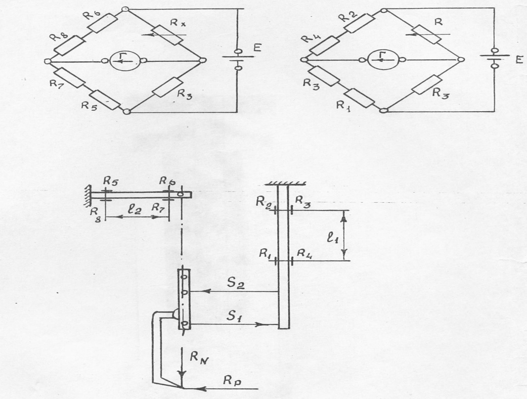
Figure 3. Diagram of attachment and joining of tensometric sensors in measuring bridges.
In case of applying the value n
> 40 value S2 –
may be taken as equal to general population variance /n
![]() /.
In order to assess the accuracy of received results dependence
determined on the basis of Student for sample variance has been used:
/.
In order to assess the accuracy of received results dependence
determined on the basis of Student for sample variance has been used:
Р -
![]()
![]()
![]() + Р -
+ Р -
![]() (4)
(4)
where: Р – is a sample average maximum value of cutting
tool force; Рг – general
average (average maximum) value of cutting tool force; S –
sample variance of random quantity; n- number of values of random
quantity; 1-р – confidence coefficient (during work the
following value was applied р = 0,95);
![]() - quantile of
- quantile of
![]() Student. Value of average cutting tool force was determined on the
basis of this formula:
Student. Value of average cutting tool force was determined on the
basis of this formula:
Рav. = 0,5 (Рmax + P min ) (5)
![]() =
=
![]()
![]()
![]() (6)
(6)
where:
![]() are variances of average, average maximum and average minimum cutting
tool force.
are variances of average, average maximum and average minimum cutting
tool force.
In course of implementation of repeated cross-section cutting the average total cutting tool force of two cuttings was determined on the basis of the following dependence::
Рtot = 0,5 (Р1av + P 2 av ) (7)
S2tot = 0,5 (S213 + S2 23 ) (8)
where: S2tot, S213, S223 – are variations of average total cutting tool force and average forces of initial and repeated cuttings.
Assessment of the soil strength in course of implementation of test research was carried out by means of portable device basis structural features of which are given in the work of Yu.A. Vetrov [1]. This portable device allows to carry out test research in filed conditions, that promotes a much higher level of assessment of plastic deformation of soil in course of cutting. The portable device is composed of a frame on which a cart travels. The cart travels forward witht the help of manual winch and rope; and later it returns to its initial position by means of rope.
The cart is composed of a frame and traveling wheels. A tape is attached to traveling axles by means of two clips, on which a knife holder is fixed. The knife, which is fixed on certain depth, may travel along rails of the knife holder. A resilient member is fixed to the knife holder, which in its turn, attached to the cart’s frame. Flexometer is fast fixed in the knife holder opposite the resilient member. In course of operation normal cutting tool force is arranged by means of clips, and the tangent line is transferred into the resilient member with the help of a lever and further recorded by vibrograph. For implementation of tests operating elements have been made, which were composed of vertical stand and step knives. Traveling speed of the operating element varied at 0,25 m/s.
For the research the areas of soil with high degree of homogeneousness were selected: strength С=18±1 impacts of plunger of DorNII; mass humidity w = 21,1% (argelit); strength С = 4±1; humidity w = 25,9% (loess-like clay).
Results of this research allowed to reveal the physics of the process of soil cutting by operating elements. Quantitative results of research underlay the selection of technical parameters of the moling ripper’s stand-knife, moles as well as shape and structural execution of the equipment.
References:
Vetrov, Yu. Utkin, A.I., Rykulo, V.I. Assessment of soil strength by means of portable device //Mining, construction and road machinery. -1970. – rev. No 10 – pp. 12-16.
Vlasov, V.V. About the law of distribution of immediate values of cutting tool force of soils and rocks //Mining, construction and road machinery. -1970. –rev.10. –pp.16-21.
Dedenko, L.G., Kerzhentsev, V.V. Mathematical treatment and preparation of test results. –Moscow: Edition of MSU. 1977. –p.11.
Neplotnik, G.Ya. Analysis of the process of excavation by means of rotor operating element with consideration of static behavior of digging resistance. //Mining, construction and road machinery 1967. –5.p.16.
