


In given are described the mathematical models of parametric DC voltage stabilizers for single and compound three structured injection-voltaic transistors.
Keywords: amplifier, the complementary emitter followers, the three-structural injection-voltaic transistor, current-voltage characteristic, amplitude-frequency characteristic
High reliability and stability of the electronic equipment is provided by the stability of the transmission characteristics of all its parts, which in turn depends on the stability of the supply voltage [1]. As exceedances and lower operating voltages are dangerous for radio equipment. In addition, to ensure the required accuracy of measuring devices (electronic voltmeters, oscilloscopes, etc.) is also required to stabilize the voltage. In light of this very topical issue is the stabilization of the power supply voltage high-current electronic equipment.
To stabilize the DC voltage commonly uses parametric voltage.
Main part
In [2,3] a complementary emitter follower is highly resistant to the action of destabilizing factors, where in the output transistors used injection voltaic transistors (IVT).
The main properties of such stabilizers are: simplicity, low efficiency (especially with variable resistance load), low coefficient of stabilization, the difficulty of obtaining an accurate value of the output voltage and control it without the use of an additional pass transistors. Parametric stabilizer can be made more powerful (increase the output current regulator) to include a zener diode in the base emitter follower circuit. One disadvantage parametric stabilizers is the output voltage dependence on temperature.
To effectively address these shortcomings, in the construction of a powerful parametric voltage regulator in order to improve its performance and stability of the operating mode to the effects of destabilizing factors (temperature, strong input ripple voltage surges load), the authors proposed to use the new components on the basis of three structured injection-voltaic transistors (TIVT) [2]. Three structured injection-voltaic transistors operate stably when the dissipated power at the collector exceeds the maximum allowable nameplate capacity of more than 3 times. TIVT works steadily at values reverse collector-emitter voltage, 4–5 times higher than a single structure, and the power dissipated in the collector, 2–3 times higher than the maximum allowed for a single transistor structures.
The scheme parametric stabilizer DC on three structural injection-voltaic transistor shown in Figure 1.
Necessary mathematical relations for the calculation of parametric stabilizer DC on TIVT [3] are as follows:
![]() ; (1)
; (1)
![]() ; (2)
; (2)
![]() ; (3)
; (3)
![]() ; (4)
; (4)
![]() . (5)
. (5)
where UZD — the operating voltage of the zener diode; UZD.RA- rated voltage of the zener diode; IZD–zener current; IZDmin — minimum current of the zener diode; RZD — impedance of zener diode; UCE — collector-emitter voltage of TIVT; UBE — base-emitter voltage ofTIVT; IR1 — current through ballast rezitor R1; IB — current base of TIVT; IBmax — maximum current base of TIVT; ILmax — maximum load current; h21EminTIVT = (h21EminVT*h21EminVT2) / (h21EminVT1+h21EminVT2) — minimum static gain of the base current of TIVT.
In particular, if the current gain of transistors VT1 and VT2 are h21EVT1 = h21EVT2 = h21E current gain of TIVT is given by:
![]() (6)
(6)
Output voltage of parametric stabilizer on a single transistor (classical scheme) to 0.6 V less than the stabilization of zener diode, and for parametric stabilizer in TIVT that value is equal to 1.2 V.
For the study and a comparative evaluation of the main characteristics of parametric voltage stabilizers on a single transistor and three structural injection- voltaic transistor voltage regulators must have the same voltage stabilization, so the stabilizers should be adjustable. Compare adjustable voltage regulators proposed to build on the basis of the controlled precision integrated zener TL431 firm Texas Instruments.
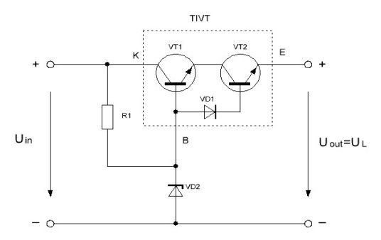
Fig. 1. Parametric DC voltage stabilizer in the three structural injection-voltaic transistor
Diagram of a parametric constant voltage stabilizer on the composite three structured injection-voltaic transistors, which have an extended range of stable operation, is shown in Fig. 2.
Necessary mathematical relations for the calculation of parametric DC voltage stabilizer on the composite TIVT are as follows:
![]() ; (7)
; (7)
![]() ; (8)
; (8)
![]() ; (9)
; (9)
![]() ; (10)
; (10)
![]() . (11)
. (11)
where UZD — the operating voltage of the zener diode; UZD.RA- rated voltage of the zener diode; IZD–zener current; IZDmin — minimum current of the zener diode; RZD — impedance of zener diode; UCE — collector-emitter voltage of TIVT; UBE — base-emitter voltage ofTIVT; IR1 — current through ballast rezitor R1; IB — current base of TIVT; IBmax — maximum current base of TIVT; ILmax — maximum load current; h21EminTIVT = (h21EminVT*h21EminVT2) / (h21EminVT1+h21EminVT2) — minimum static gain of the base current of TIVT.
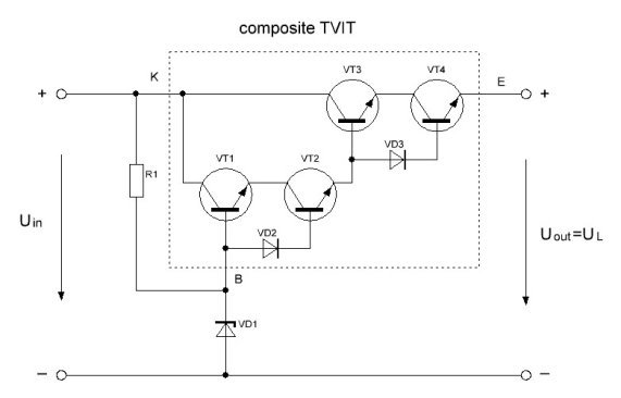
Fig. 2. Parametric DC voltage stabilizer for composite three structured injection-voltaic transistors connected in a Darlington diagram
In particular, if the current gain of the transistors VT1 and VT2 are h21EVT1 = h21EVT2 = h21EVT3 = h21EVT4 = h21E current gain of TIVT is given by:
![]() . (12)
. (12)
Output voltage stabilizer for composite parametric three structured injection-voltaic transistors is less than zener voltage 2.4 V.
References:
- A. V. Vasilkov, I. A. Vasilkov. Power Sources-M.: Forum, 2012. P. 235
- Provisional Patent of Uzbekistan № IDP 04949. Composite bipolar transistor/ H. K. Aripov, H. H. Bustani, S. S. Kasimov, A.AYarmukhamedov //. Bulletin № 5, 31.10.2001.
- Provisional Patent of Uzbekistan № IDP 04950. Composite bipolar transistor / H. K. Aripov, H. H. Bustani, S. S. Kasimov, A.AYarmukhamedov //. Bulletin № 5, 31.10.2001.
- Предварительный патент РУз № 5123. Трехструктурный инжекционно-вольтаический транзистор / Арипов Х. К., Бустанов Х. Х., Мавлянов А. Р., Махсудов Д. Т. //. Бюлл. № 2, 30.06.1998.
- Фазилжанов И. Р. Комплементарный эмиттерный повторитель на трехструктурных инжекционно-вольтаических транзисторах // Республиканская научно- техническая конференция аспирантов, магистров и бакалавров «Информационно-коммуникационные технологии». Сб. докладов. — Ташкент, 2008.- C. 196.
