


Direct digital synthesis (DDS) is a powerful method used in the generation of radio frequency signals for apply in a variety of applications from radio receivers to signals generators and various other. The method has become widespread in recent years with the advances being made in integrated circuit technology that allow much faster speeds to be handled which in turn enable higher frequency DDS chips to be made. [6] DDS synthesizes the waveform data in digital processing and the data is converted to analog signal with a DAC.
This is technique called DDS, because it generates the waveform with a digital circuit. It has very good stability, accuracy and reproducibility compared to the analog method, and can be fully controlled by software. [2]
DDS technique makes periodical waveform generation possible as well as a sine wave generation based on sample value is loaded into the internal look-up table module in the DDS, the periodical waveform with desired frequency and phase can be generated.
A common method for digitally generating a sinusoid employer a lookup table scheme. [4] The lookup table stores samples of sinusoid. A digital integrator is used to generate a suitable phase argument that is mapped by the lookup table to the desired output waveform
Summarize why DDS is a valuable technique.
1) The tuning resolution can be made arbitrary small to satisfy almost any design specification.
2) The phase and the frequency of the waveform can be controlled in one sample period, making phase modulation feasible.
3) The DDS implementation relies upon integer arithmetic, allowing implementation on virtually any microcontroller.
4) The DDS implementation is always stable, even with finite-length control words. There is no need for automatic gain control.
5) The phase continuity is preserved whenever the frequency is changed. [1] [5]
The actual implementation of DDS requires a look-up table to determine the phase output signal at any point in time.
The following figure 1 shows the building blocks for DDS.
A fundamental problem with this simple DDS system is that the final output frequency can be changed only by changing the reference clock frequency or by reprogramming the PROM, making it rather inflexible. [6]
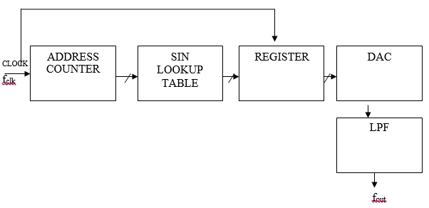
Figure 1: DDS system
The output frequency, f out, of the DDS waveform is a function of the system clock frequency, f clk, the phase width, that is, number of bits in phase accumulator, N, and the phase increment value M. The output frequency in Hertz is defined by:
![]()
In order to have better frequency resolution, the number of bits employed in the phase accumulator is increased.
![]()
At each reference clock cycle, the phase accumulator integrates the phase increment value to the phase accumulator output value. [6] The phase increment and accumulator output value are defined by the same number of bits. The full precision of the phase accumulator can not be used to index the lookup table, because of very large memory requirement. [7] For this reason the phase accumulator output is quantized by filtering lest significant bits. The quantization depends on the lookup table length. For calculate all parameters was used number of phase truncation bits, because of reason that value for address inside of lookup table
There are also two parameters which have effect on the quality of the waveform: lookup table length (number of phase truncation bits) and lookup table width (number of amplitude truncation bits). If the value of these parameters is increased, the output waveform resolution becomes better.
The truncated output of the phase accumulator server as the address to a sine lookup table. Each address in the lookup table corresponds to a phase point on the sine wave from 00 to 3600. [3] The lookup table contains the corresponding digital amplitude information for one complete cycle of a sine wave. The lookup table therefore maps the phase information from the phase accumulator into a digital amplitude word.
In order to generate a periodical waveform at a output frequency, a constant phase increment is added to the phase accumulator at each reference clock cycle. A waveform at higher frequency can be generated if the phase increment value is larger.
DDS allows represent desired frequency that depends of phase accumulator and clock frequency, all this parameters can be increased for greater accuracy. Phase truncation (applying lookup table) helps to reduce power consumption.
DDS, which generates analog waveform with digitally adjustable high resolution phase and frequency, is useful in wide variety of application.
References:
- Dr.R. K. Sharma and Gargi Upadhyaya “Memory Reduced and Fast DDS Using FPGA”, International Journal of Computer Theory and Engineering, Vol 2,No.4,August,2010.
- DDS Design, By David Brandon, EDN, May 13, 2004.
- Henry T. Nicholas, III and Henry Samueli, «An Analysis of the Output Spectrum of Direct Digital Frequency Synthesizers in the Presence of Phase-Accumulator Truncation», IEEE 41st Annual Frequency Control Symposium Digest of Papers, 1987, pp. 495–502, IEEE Publication No. CH2427–3/87/0000–495.
- Lionel Cordesses, “Direct Digital Synthesis: a tool for Periodic Wave Generator” (Part I), in IEEE signal processing magazine, July 2004
- Manjiri A.Bopche,Dr A. Y. Deshmukh “FPGA based DDS function generator” International Journal of VLSI and Signal Processing Applications,Vol.1,Issue 2,May 2011,(8–14),ISSN 2231–3133.
- Tutorial " Fundamentals of Direct Digital Synthesis (DDS) " MT-085
- Xilinx ds558 march 1,2011
